Multi-core transformer plasma source

a transformer and plasma source technology, applied in the direction of electric discharge tubes, chemical vapor deposition coatings, coatings, etc., can solve the problems of non-uniform plasma density, device or material compatibility with this type of plasma formation, and create defects, so as to minimize the erosion of the inner nozzle material, improve the effect of extraction gradient, and improve the effect of ion flux

Inactive Publication Date: 2008-04-29
APPLIED MATERIALS INC
View PDF35 Cites 35 Cited by
  • Summary
  • Abstract
  • Description
  • Claims
  • Application Information

AI Technical Summary

Benefits of technology

[0011]A multi-core plasma source forms a number of poloidal plasma currents. In some embodiments, the cores are essentially parallel to each other, i.e. the center axis of the core tori are essentially parallel to each other in a “flat” configuration. In other embodiments, the cores are in a series, or “stacked” configuration. In one flat configuration, a number of relatively small plasma-generating transformer cores are arrayed across a double-walled panel. The panel has a number of through holes, some surrounded by transformer cores, and some providing a return path for the plasma generated by the cores. The panel provides a uniform plasma across a relatively large surface area, and can be scaled to larger sizes. Similarly, plasma uniformity can be improved by increasing the number of cores and through holes. The multi-core panel can be driven by a variety of AC, radio-frequency (“RF”), or microwave (“MW”) sources. The transformers efficiently generate plasma from a variety of precursors over a wide range of pressures. In another embodiment, the panel is curved, rather than flat.
[0014]In yet another embodiment, an ion source for an ion implantation system utilizes the directional nature of the ion distribution along the centerline of the toroidal plasma generators by ejecting a portion of the ions produced toward extraction electrodes. This is believed to allow optimizing extraction gradients for mass / charge analyzer performance while providing a high ion flux for implantation.
[0015]In yet another embodiment, a toroidal plasma generator is placed in a plasma torch head. The plasma generator is encased within an inner nozzle, thus protecting the operator from electrical shock hazard. The poloidal current flow minimizes erosion of the inner nozzle material. It is believed that the toroidal plasma generator will produce plasma from a wide variety of precursors over wider pressure ranges and flow rates than conventional arc-discharge plasma generators.
[0016]In yet another embodiment, an ion source for an ion milling system utilizes the directional nature of the ion distribution along the centerline of the toroidal plasma generators by ejecting a portion of the ions produced toward accelerator plates. It is believed that the transformer-coupled toroidal plasma generator will provide a high flux of ions and that the high-density nature of the plasma along the centerline will improve the performance of the ion milling system.

Problems solved by technology

However, some devices or materials might not be compatible with this type of plasma formation, particularly the bombardment by plasma species, including high-energy photons, and associated heating of the substrate.
This field component acting on the plasma can cause physical erosion (“sputtering”) of the inside of the dome, as well as affect the power coupling to the plasma, thus causing a non-uniform plasma density.
In some instances the plasma might contain species that react with the material of the dome, further eroding the dome and potentially creating particles than can fall from the dome onto the wafer, creating defects.
If erosion of the inner surface of the dome continues to a point where particulate contamination or strength of the dome is an issue, the dome might have to be replaced, affecting throughput of the plasma system, and potentially disrupting the product flow through an entire fabrication line.
However, recombination of plasma species on the surface of the tubes or in the gas / plasma mixture can reduce the effectiveness of a plasma source.
Uniformity problems are generally greater with larger-sized wafers.

Method used


Image

  • Multi-core transformer plasma source
  • Multi-core transformer plasma source
  • Multi-core transformer plasma source

Examples


Embodiment Construction

I. Introduction

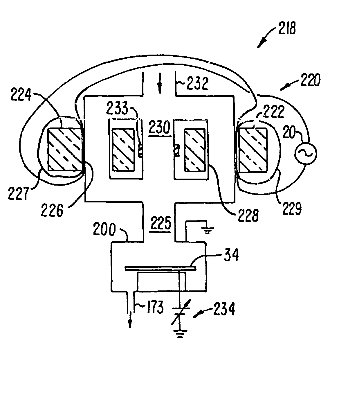
[0042]Embodiments of the present invention produce a plasma from multiple cores to achieve various beneficial effects. In one embodiment, many small cores are used to achieve a uniform plasma over a large surface area. In another embodiment, multiple cores are used to provide a high plasma density with a compact, efficient plasma generator. In another embodiment, the directionality of the plasma is used to provide an efficient source of ions for ion implantation. In yet another embodiment, the temperature profile of the plasma across the center of the core provides a compact, efficient plasma torch. These and other aspects of the invention will be further understood in light of the specific embodiments discussed below and reference to the accompanying figures. It is understood that other embodiments may be utilized and structural changes may be made without departing from the scope of the present invention.

II. Exemplary Substrate Processing System

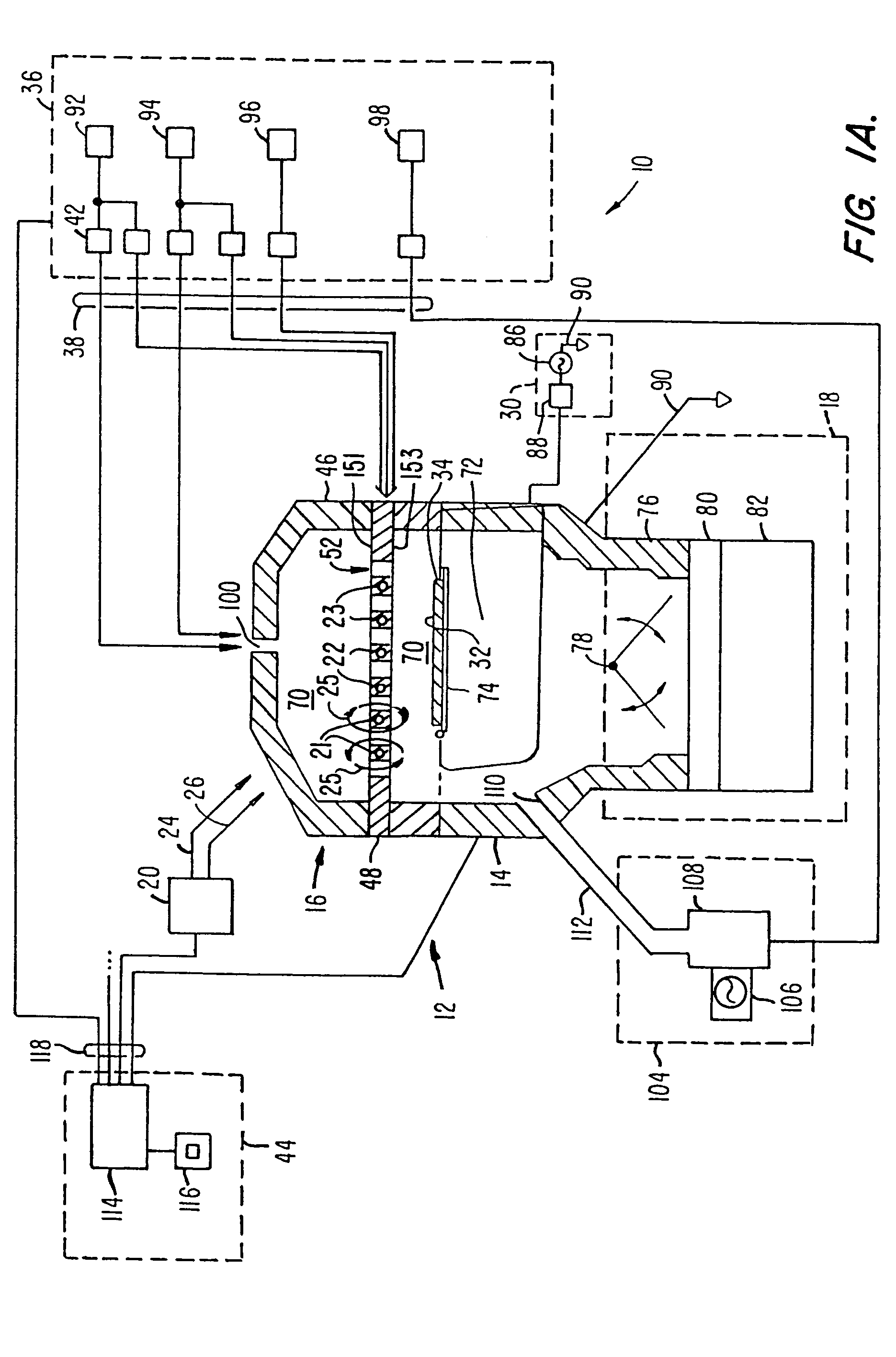
[0043]FIG. 1A illustr...


PUM

PropertyMeasurementUnit
Dielectric polarization enthalpyaaaaaaaaaa
Magnetic energyaaaaaaaaaa
Currentaaaaaaaaaa

Abstract

A transformer-coupled plasma source using toroidal cores forms a plasma with a high-density of ions along the center axis of the torus. In one embodiment, cores of a plasma generator are stacked in a vertical alignment to enhance the directionality of the plasma and generation efficiency. In another embodiment, cores are arranged in a lateral array into a plasma generating plate that can be scaled to accommodate substrates of various sizes, including very large substrates. The symmetry of the plasma attained allows simultaneous processing of two substrates, one on either side of the plasma generator.

Description

CROSS REFERENCE TO RELATED APPLICATION[0001]This application is a divisional of U.S. patent application Ser. No. 09 / 839,360, entitled “MULTI-CORE TRANSFORMER PLASMA SOURCE,” filed Apr. 20, 2001 now U.S. Pat. No. 6,755,150, the entire disclosure of which is incorporated herein by reference for all purposes.BACKGROUND OF THE INVENTION[0002]Plasmas are used for a variety of purposes in the fabrication of semiconductor devices, such as integrated circuits, and other types of substrates, such as micro-electro-mechanical (“MEMs”) substrates to achieve a variety of results. Plasma methods include the formation of a layer using plasma-enhanced chemical vapor deposition and etching techniques, such as reactive ion etching. A plasma might also be used to clean a processing chamber, or to prepare a surface of a substrate for a subsequent process step, such as a plasma wafer surface clean or activation prior to formation of a layer on the surface. Plasma generators are also used as a source of ...

Claims


Application Information

Patent Timeline
IPC IPC(8): C23C16/00C23F1/00H01L21/3065H01J37/32
CPCH01J37/32431
Inventor LAI, CANFENGCOX, MICHAEL S.LOEWENHARDT, PETER K.TANAKA, TSUTOMUSHAMOUILIAN, SHAMOUIL
Owner APPLIED MATERIALS INC
Why Eureka
Try Eureka