
Apparatus and method for osmotic membrane distillation

Inactive Publication Date: 2008-04-22
CHEMETICS
View PDF14 Cites 5 Cited by
  • Summary
  • Abstract
  • Description
  • Claims
  • Application Information

AI Technical Summary

Benefits of technology

"The patent text describes a method for efficiently concentrating and diluting heavy chemical solutions using osmotic membrane distillation (OMD). The method can be carried out at commercially-acceptable rates and can provide cost advantages compared to other methods. The process involves contacting a process solution with a more concentrated solution to remove water vapor through a membrane. The resultant solution can then be recycled back to the heavy chemical plant for further use. The method can be used in various heavy chemical plants and can be adapted to different chemicals and processes. Overall, the method provides a valuable tool for recycling and re-concentration in heavy chemical production."

Problems solved by technology

More specifically, the term “heavy chemical” in this specification is also restricted to the production of inorganic chemicals when manufactured in a heavy chemical process plant.

Method used


Image

  • Apparatus and method for osmotic membrane distillation
  • Apparatus and method for osmotic membrane distillation
  • Apparatus and method for osmotic membrane distillation

Examples


example 1

[0095]Spent brine (18% w / w NaCl) was pumped on the shell side of Microza® unit at 2.7 ml / min (linear velocity: ˜0.5 cm / sec), while 30.5% w / w NaOH Receiver solution was pumped through the lumen side of the PVDF capillaries at 2.5 ml / min (linear velocity in each capillary ˜1.2 cm / sec). Spent brine and Receiver temperatures were varied but kept equal to each other. In the process the Spent brine became concentrated to the 25-26% w / w level. The estimated initial differential water vapor pressure difference (driving force) was 0.080 bar at 30° C. and 0.080 bar at 60° C., respectively. The measured water transfer rates were as follows:

[0096]

Temperature, ° C.H2O transfer rate, kg / m2 hr220.42350.80451.00551.25651.50

example 2

[0097]Conditions were similar to that in Example 1 except that the temperature was fixed to 73° C. and the lumen side flow was increased to 7.6 ml / sec (˜3.5 cm / sec), while the shell side flow (Spent brine) was varied. The measured water transfer rates were as follows:

[0098]

Shell side flow, ml / secH2O transfer rate, kg / m2 hr6.62.258.52.9010.03.30

example 3

[0099]Gore-Tex® tubular PTFE® membranes were used in a membrane contactor of the undisclosed flow-type configuration for OMD process. Some description of the membrane module and membranes are given in Table 1.

[0100]

TABLE 1Gore-Tex tubular membranes and a membrane module used in theexperiments.Membrane form / materialTubes / PTFEActive area of the membrane module based on the1.1m2tube-sideActive tube length43.1cmPorosity of membranes~50%Membrane tube ID~0.55mmMembrane tube OD~0.80mmMembrane tube thickness~0.125mm

[0101]Spent brine (17.5 wt.% NaCl) was pumped on the shell side of the membrane contactor comprising Gore-Tex tubular membranes at a linear velocity of ˜7.4 cm / sec. Receiver solution comprising 30% NaOH was pumped through the tube-side of the PTFE tubular membranes at a linear velocity of ˜21 cm / sec per each tube. Spent brine and Receiver temperatures were varied but kept equal to each other (see a table further below):

[0102]

Temperature, ° C.H2O transfer rate, kg / m2 hr501.24603.8...


PUM

PropertyMeasurementUnit
boiling pointaaaaaaaaaa
temperatureaaaaaaaaaa

Abstract

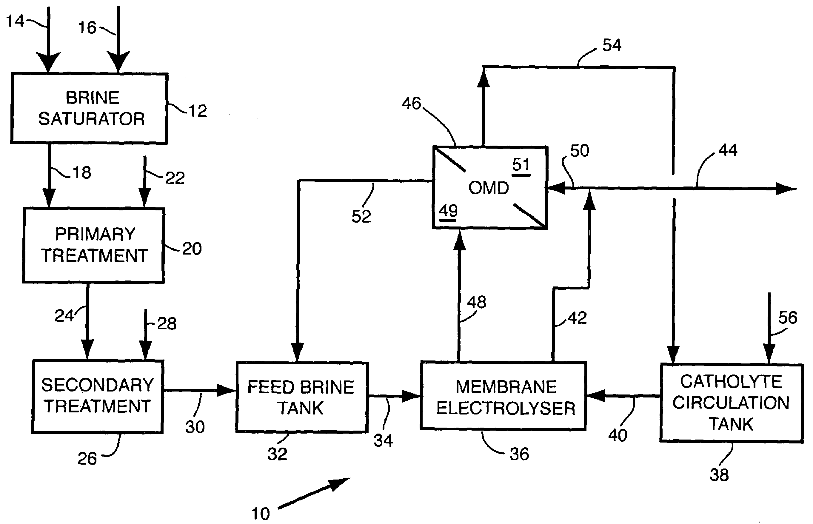
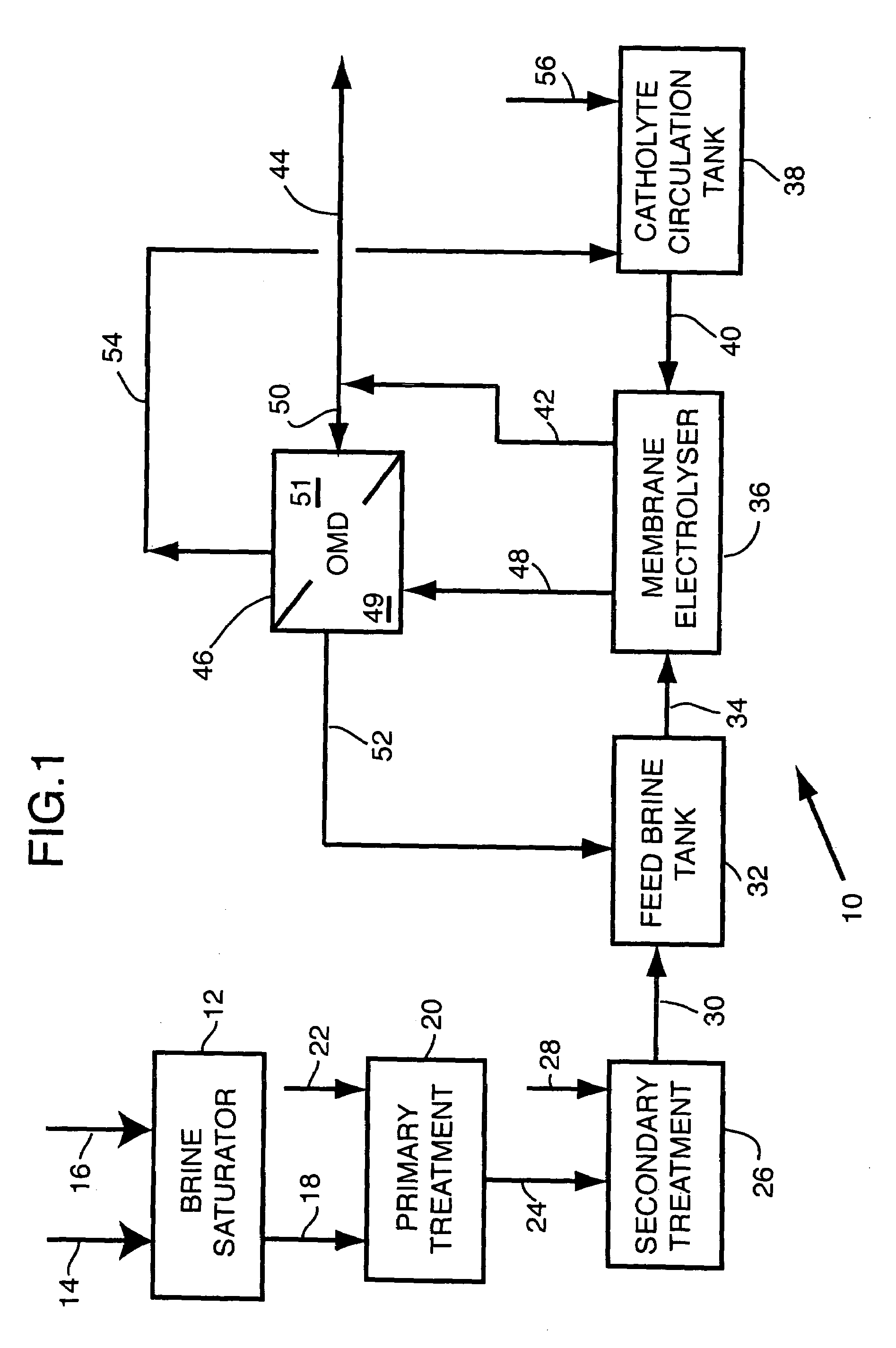
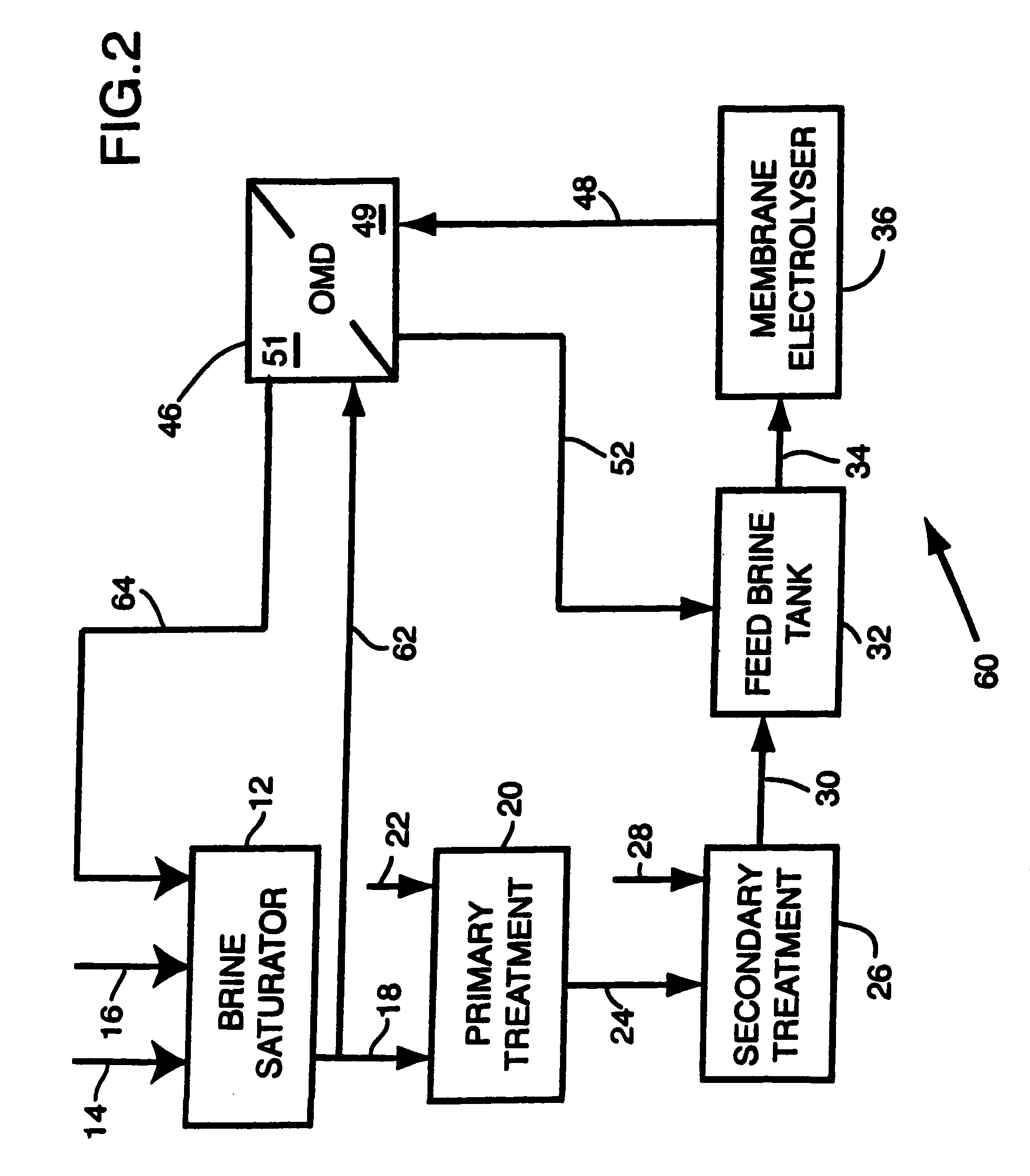
A method of enhancing the concentration of a first inorganic compound in a first aqueous solution of a first process of a heavy chemical plant, the method comprising (a) feeding the first solution having the first compound at a first concentration and a first water vapor pressure to an osmotic membrane distillation means comprising a hydrophobic, gas and water vapor permeable membrane separating (i) a first chamber for receiving the first solution, from (ii) a second chamber for receiving a receiver feed aqueous solution having a second water vapor pressure lower than the first water vapor pressure; (b) feeding the receiver aqueous feed solution to the second chamber as to effect transfer of water vapor through the membrane from the first chamber to the second chamber, and to produce (i) a resultant first solution having a second concentration of the first compound greater than the first concentration and (ii) a diluted receiver feed aqueous solution; and (c) collecting the resultant first solution. The apparatus and method are of particular value in electrolytic haloalkali production plants in offering reduced capital and operating re-concentration and dilution costs.

Description

FIELD OF THE INVENTION[0001]This invention relates to apparatus and method for the recovery and concentration of heavy chemical liquors using osmotic membrane distillation, particularly spent alkali metal halide solutions from electrolytic cells and more particularly, spent sodium chloride solutions from the production of sodium hydroxide and chlorine gas.BACKGROUND TO THE INVENTION[0002]In the process of production of chlorine and caustic, a nearly saturated NaCl brine solution is fed to an electrolyzer, where upon application of DC current, chlorine gas is evolved at the anode while water is electrochemically reduced to gaseous hydrogen and hydroxyl ions at the cathode. Anode and cathode are typically separated by a microporous diaphragm or perfluorinated cation exchange membrane such as those known under the trademarks, Nafion®, Flemion® or Aciplex®. Some chloralkali plants may still utilize the older mercury-based process, in which there is no separator between the electrodes an...

Claims


Application Information

Patent Timeline
Patent Type & Authority Patents(United States)
IPC IPC(8): B01D61/36C25B1/00C25B1/14C25B1/24B01D63/00C01B17/88C25B15/08
CPCB01D61/364C01B17/88C25B15/08
Inventor TWARDOWSKI, ZBIGNIEWDRACKETT, THOMAS S.BESSARABOV, DMITRIFETISSOFF, PETER E.
Owner CHEMETICS
Learn More