
Electrical connector and liquid crystal display device

a technology of liquid crystal display device and connector, which is applied in the direction of coupling contact member, coupling device connection, instruments, etc., can solve the problems of troublesome soldering, and inability to reliably perform electrical connection between the contact and the terminal. , to achieve the effect of reliably performing electrical connection between the contact and the terminal

Inactive Publication Date: 2008-03-18
JST MFG CO LTD
View PDF17 Cites 24 Cited by
  • Summary
  • Abstract
  • Description
  • Claims
  • Application Information

AI Technical Summary

Benefits of technology

The present invention is an electrical connector with an insulating housing, a contact, and an operating member. The contact has elastic pieces that face each other and are exposed to the insertion recess of the housing. The elastic pieces have clamp portions for clamping the terminal in predetermined directions. The operating member has a widening operating portion for widening the distance between the clamp portions of the contact. This allows for easy insertion of the terminal between the clamp portions and ensures a reliable electrical connection between the contact and the terminal.

Problems solved by technology

However, in the documents 1 and 2, a continuity failure may occur between the terminal and the connection fitting due to defective soldering.
In addition, the soldering is troublesome.
Therefore, enormous labor is required for soldering.
Not only the case of using a cold cathode fluorescent tube but also cases of using other fluorescent tubes such as an external electrode fluorescent tube or using a shaft-like terminal other than the fluorescent tubes also have a similar problem.

Method used


Image

  • Electrical connector and liquid crystal display device
  • Electrical connector and liquid crystal display device
  • Electrical connector and liquid crystal display device

Examples


Embodiment Construction

[0029]A preferred embodiment of the present invention will be described with reference to the accompanying drawings.

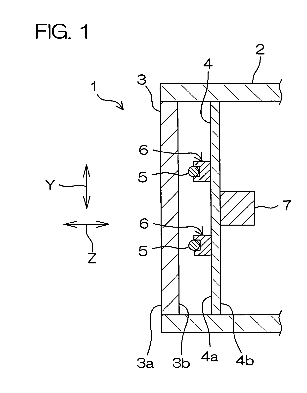
[0030]FIG. 1 is a schematic sectional view showing a general construction of a liquid crystal display device including an electrical connector according to an embodiment of the present invention. Referring to FIG. 1, the liquid crystal display device 1 is used as, for example, a monitor of a television or a personal computer.

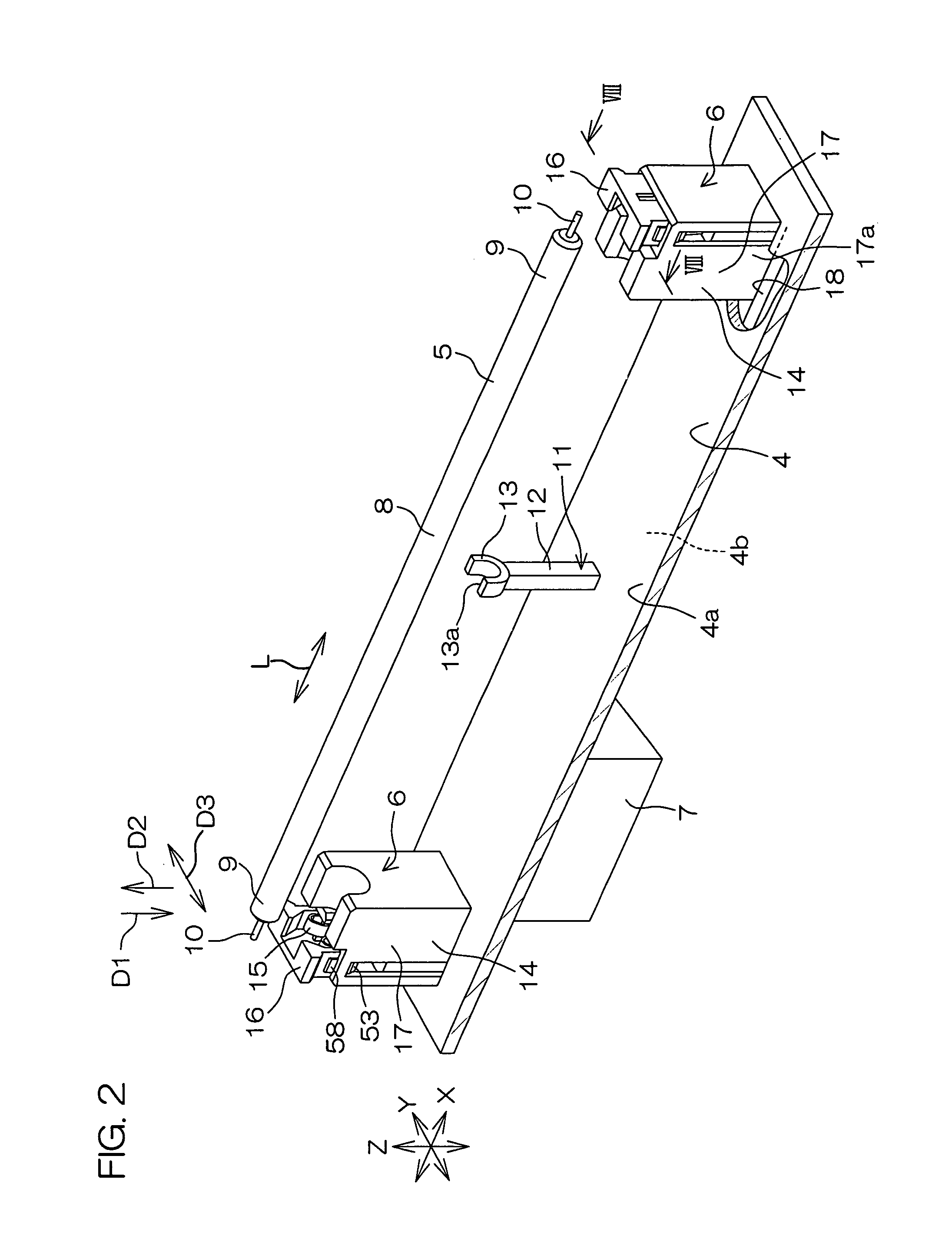
[0031]The liquid crystal display device 1 includes a casing 2, a liquid crystal panel 3, a circuit board 4 disposed in the rear of the liquid crystal panel 3, a plurality of cold cathode fluorescent tubes 5 as fluorescent tubes, electrical connectors 6 (hereinafter, simply referred to as connectors), and an inverter circuit 7.

[0032]The liquid crystal panel 3 is a non light-emitting display panel, and is attached to an opening on the front of the casing 2. The front face 3a of the liquid crystal panel 3 faces forward of the casing 2, and the back fa...


PUM


Abstract

An electrical connector has a contact held by a housing and an operating member for operating the contact. The housing includes an insertion recess into which a shaft-like terminal is inserted along a first direction. A pair of elastic pieces of the contact respectively include clamp portions for clipping the terminal in predetermined clamping directions orthogonal to the first direction. The first direction is along a radial direction of the terminal. The operating member includes a widening operating portion for widening the distance between the clamp portions of the pair of elastic pieces.

Description

BACKGROUND OF THE INVENTION[0001]1. Field of the Invention[0002]The present invention relates to an electrical connector which is connected to a fluorescent tube for a backlight of a liquid crystal display device, etc., and a liquid crystal display device including the same.[0003]2. Description of Related Arts[0004]For example, as a connecting structure of a terminal of a fluorescent tube such as a cold cathode fluorescent tube to be used as a backlight of a liquid crystal display type television or monitor, the following documents 1 and 2 have been proposed:[0005]Document 1: Japanese Unexamined Patent Publication No. 2001-250605 (date of publication: Sep. 14, 2001)[0006]Document 2: Japanese Unexamined Patent Publication No. 2004-259645 (date of publication: Sep. 16, 2004)[0007]In the documents 1 and 2, a connection fitting fixed to one end of an electric wire is soldered to a terminal (electrode) of a cold cathode fluorescent tube. The other end of the electric wire is connected to...

Claims


Application Information

Patent Timeline
Patent Type & Authority Patents(United States)
IPC IPC(8): H01R33/02
CPCG02F1/133604G02F1/133608H01R13/193H01R33/02G02F2001/133612H01R33/0827G02F1/133612H01R13/11H01R33/08G02F1/1345H01R4/28
Inventor MIYAZONO, KATSUNORI
Owner JST MFG CO LTD
Learn More