
Remote visual feedback of collimated area and snapshot of exposed patient area

a collimated area and remote visual feedback technology, applied in the field of medical xray imaging, can solve the problems of insufficient distance adjustment or proper distance adjustment between the patient and the x-ray source, cumbersome and time-consuming saving settings, double work, etc., to improve patient throughput, reduce patient and/or clinician exposure, and reduce dose levels

Inactive Publication Date: 2008-03-18
SIEMENS HEALTHCARE GMBH
View PDF11 Cites 27 Cited by
  • Summary
  • Abstract
  • Description
  • Claims
  • Application Information

AI Technical Summary

Benefits of technology

The invention is an X-ray examination system that includes a camera to image the same FOV as the X-ray beam in a patient's fixed position. This camera allows the operator to determine the proper FOV and adjust the patient and system elements accordingly. The system also includes an X-ray imaging device to capture latent image frames of a region of interest within the patient's anatomy. An image processing chain processes the latent image frames and a display device displays the post-processed image frames as an X-ray diagnostic image. The feedback signal from the camera controls the collimator assembly and the position of the X-ray tube and imaging device. The camera image is displayed with the X-ray image during normal imaging operation and is particularly useful during pre-test or physical set-up operation. The camera is preferably a video camera and is preferably miniaturized. The system includes a focusing system to focus the camera FOV. The technical effects of this invention include improved patient throughput, reduced patient and clinician exposure to unnecessary X-ray exposure, reduced dose levels overall due to improved collimator adjustment, and improved image quality.

Problems solved by technology

For that matter, because manually setting the collimator parameters, such as at each station in an angiographic study of leg vasculature for a mask run, and saving the settings is cumbersome and time consuming, automatic collimator adjustment functions have been developed.
But collimator adjusting or adjusting proper distances between the patient and X-ray source may be insufficient nevertheless where the patient or table has moved after set-up.
Required readjustment of a patient who has moved between system physical adjustment and diagnostic or interventional imaging causes double work, in which the clinician is required to reposition the patient, and possibly recalibrate.
Where readjustment is required after setup and test imaging, the patient, and possibly the clinician are exposed to unnecessary radiation where the test imaging must be repeated, or the examination is inadvertently conducted with an improper FOV.
Again there is a cost in patient throughput time, clinician time and energy, and cost.
In addition, where a clinician may wish an alternative X-ray image based on a first image, or a series of images of a fixed patient FOV, repositioning is complicated if the patient has moved without the clinician realizing it until the “next” image is viewed.

Method used


Image

  • Remote visual feedback of collimated area and snapshot of exposed patient area
  • Remote visual feedback of collimated area and snapshot of exposed patient area
  • Remote visual feedback of collimated area and snapshot of exposed patient area

Examples


Embodiment Construction

[0021]Reference will now be made in detail to exemplary embodiments of the present invention, examples of which are illustrated in the accompanying drawings, wherein like reference numerals refer to like elements throughout.

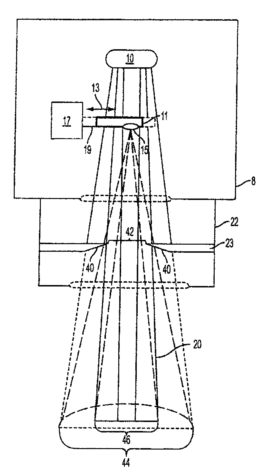
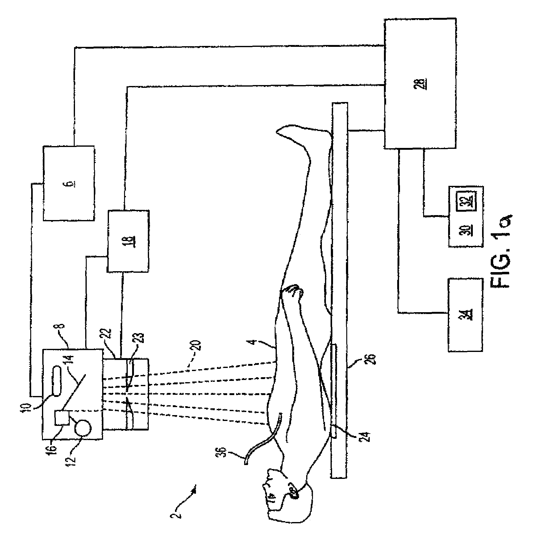
[0022]FIG. 1a represents an X-ray diagnostic imaging system 2 of the invention, under which is a patient 4 undergoing an X-ray examination procedure. The X-ray system 2 includes a high voltage transformer assembly 6, an X-ray source housing 8, comprising an X-ray tube 10, a camera 12, mirror 14 and mirror drive device 16. The X-ray source housing 8 is attached to a collimator assembly 22, including beam-limiting filter plates 23. The mirror drive device controls the positioning of mirror 14 into and out of the path of an X-ray beam 20, from X-ray tube 10, controls camera positioning and operation, and exchanges mirror position and camera position information with the system through position detecting and control device 18. With respect to the camera and mirror, m...


PUM


Abstract

A method and system are providing for performing X-ray diagnostic imaging using a camera image controlled to image a field of view (FOV) that is substantially coincident and coplanar with a radiation footprint or FOV of an X-ray beam radiated towards a patient under examination. Both the X-ray beam and camera FOVs are shaped and / or limited by collimation. The method and system include acquiring a camera image with a collimated FOV to an X-ray beam FOV before X-ray imaging a patient, displaying the camera image and adjusting the collimation and patient positioning to define the X-ray beam FOV based on the displayed camera image before X-ray imaging the patient. After adjustment, the method and system include radiating the X-ray beam as collimated during the patient X-ray imaging, acquiring and processing captured X-ray image information to reconstruct an X-ray image and displaying the reconstructed X-ray image with the displayed camera image. The step of radiating may be postponed or interrupted for X-ray beam readjustment or patient repositioning for desired X-ray imaging based on the camera image displayed.

Description

PRIORITY CLAIM TO RELATED APPLICATION[0001]This application claims priority from U.S. Provisional Patent Application Ser. No. 60 / 834,680, filed Aug. 1, 2006, the disclosure of which is incorporated by reference in its entirety herein.BACKGROUND OF THE INVENTION[0002]1. Field of the Invention[0003]The present invention relates to medical X-ray imaging, and more particularly the present invention relates to an X-ray system that includes a camera to provide visual feedback to an operator of the system during pre-examination testing and adjustment, including a snapshot of a collimator-shaped patient FOV. In an embodiment, a camera image is provided by the camera to the X-ray system, and a feedback signal is generated in response to the camera image to support collimator and / or X-ray tube adjustment, patient positioning and movement, etc.[0004]2. Description of the Related Art[0005]X-ray imaging systems for digital radiography are used for conventional imaging of anatomical background in...

Claims


Application Information

Patent Timeline
Patent Type & Authority Patents(United States)
IPC IPC(8): A61B6/08
CPCA61B6/08A61B6/469
Inventor KUZMANOVIC, MILJAN
Owner SIEMENS HEALTHCARE GMBH
Learn More