
Silcon carbide element

a silicon carbide and heating element technology, applied in the direction of non-adjustable resistors, combustion processes, combustion ignition, etc., can solve the problems of low mechanical loadability, insufficient densification, undesirable grain growth, etc., and achieve the effect of increasing the specific resistance, increasing the resistance per length, and increasing the specific resistan

Inactive Publication Date: 2008-03-11
HEUBERGER MARTIN
View PDF23 Cites 13 Cited by
  • Summary
  • Abstract
  • Description
  • Claims
  • Application Information

AI Technical Summary

Benefits of technology

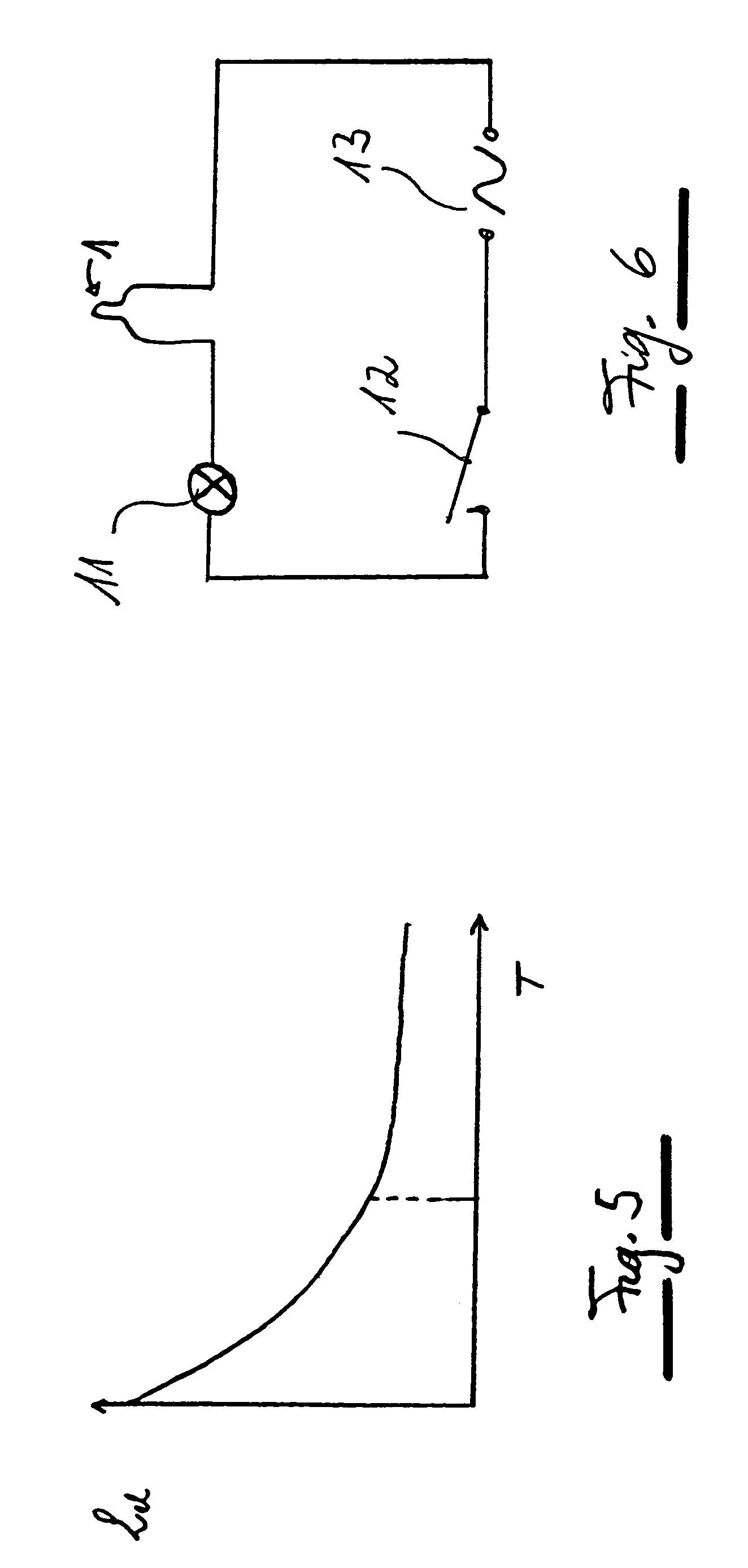
[0012]For ignition elements such as oil furnaces, as well as for electric igniters for oil or gas burners and the like, it is normally sufficient if the segment resistance changes only a minimal amount with further increasing current. It was recognized that, especially with electric igniters that are operated for only a short time, and which are shut off after ignition, a quasi-stable characteristic behavior can be achieved even when the resistance changes slightly with increasing current.
[0013]Advantageously, the ceramic heating element arrangement may be used in an oil igniter which is heated on a single-story heating installation immediately above an oil storage tank or in a small quantity of oil, since the achievable glow temperatures are sufficient to avoid contamination and / or destruction of the surface by coking substances.
[0015]The ceramic electric ignition element may be particularly designed for temperatures at the hottest point in the range above 500° C., in particular 1,100° C. For oil and / or gas burner igniters, temperatures around 1,400-1,500° C. are used at this point. The limiting segment may be provided as part of the ceramic heating element, and especially at its warmest point. This can be achieved if the segment has a higher resistance per length than other regions of the ceramic heating element. For this purpose, either the segment may be narrower or thinner than other parts of the ceramic heating element and / or the specific resistance of the segment may be increased. Such a design of a ceramic heating element, in which different regions or segments have different electrical and / or thermal properties, can be advantageous in and of itself, independently of the electrical activation.
[0016]According to the present invention, an increase in the specific resistance may be achieved by changing the segment close to the surface or at the surface, in comparison with the rest of the ceramic heating element. This surface treatment can avoid possible problems with making changes to overall geometrical dimensions, because a reduction of the thickness of the ceramic heating element below certain limits can endanger mechanical stability in certain cases.
[0017]In particular, the conductivity of the surface materials may be raised by nitrogen doping. It was recognized that, during treatment of the sintered, fine-pored element in a nitrogen-CO atmosphere, the doping nitrogen, which raises the conductivity of the sintered element, remains primarily near the surface. That is, a nitrogen gradient develops which may be attributed to the great density of the ceramic parent substance. In nitrogen doping by introduction of the ceramic heating element into an N2—CO atmosphere at elevated temperature, the segment resistance can be increased due to the better conducting nitrogen layer is removed or due to the fact that right from the beginning, doping with nitrogen is carried out in such a way that a reduced quantity of nitrogen is present at the segment. This can be achieved, for example, by sealing the segment with inert substances before diffusing nitrogen into the SiC element, for which inert substances impervious to gas may be used, or by doping via powders which selectively liberate nitrogen. The powders have a larger grain size (i.e. a smaller specific surface) do not need to be situated at the segment or not at all at the segment, but because they trap nitrogen, they may be arranged in the vicinity of the segment in large quantities. Such ceramic heating elements provide various embodiments of the ceramic heating element, in which different regions or segments have different electrical and / or thermal properties, which are advantageous per se, independently of the electrical activation. In an embodiment of the ceramic heating element, the tip of the ceramic heating element, for example, of a ceramic electric igniter, has a low specific conductivity because of high density and the low doping depth generated by the sintering method, whereas at the shank a lower density with a higher doping depth is set in order to achieve lower ohmic heating by a greater specific conductivity. This brings about an industrially applicable ceramic heating element having an optimal temperature profile and a thermally less-stressed mounting support.

Problems solved by technology

Frequently, the silicon carbide elements are not very dense but large-pored, which leads to a low mechanical loadability.
It is also mentioned that normal grain growth occurs sooner in SiC—Al—C systems than in SiB—B—C systems, namely at a sintering temperature higher than about 2,050° C., and that this grain growth is undesirable because of deterioration of mechanical properties.
It is also mentioned that, while it is true that good electrical conductivity may be achieved by doping agents such as aluminum nitride, molybdenum disilicide, phosphorus, arsenic and antimony, the sintering behavior of the ceramic is, however, influenced unfavorably by these additives, so that sufficient densification can be achieved only by pressure-supported sintering methods such as hot pressing or high-temperature isostatic pressing.
A disadvantage of the described arrangement is that the conventional SiC ceramics discussed in the reference have a negative temperature coefficient.
Because of the rapidly decreasing resistance of the conventional SiC ceramic heating elements having NTC(Negative temperature coefficient) properties, the igniter element and its mounting fixture heat up to undesirably high temperatures far above the ignition temperature.
This may impair the electrical contacting and / or lead to sparkover.
Attempts at integrating the NTC properties into the ceramic by fitting in a conductor having PTC properties can make hot pressing a necessary procedure, which impairs shaping.
This automatically leads to a limiting action.
This surface treatment can avoid possible problems with making changes to overall geometrical dimensions, because a reduction of the thickness of the ceramic heating element below certain limits can endanger mechanical stability in certain cases.

Method used


Image

  • Silcon carbide element
  • Silcon carbide element
  • Silcon carbide element

Examples


Embodiment Construction

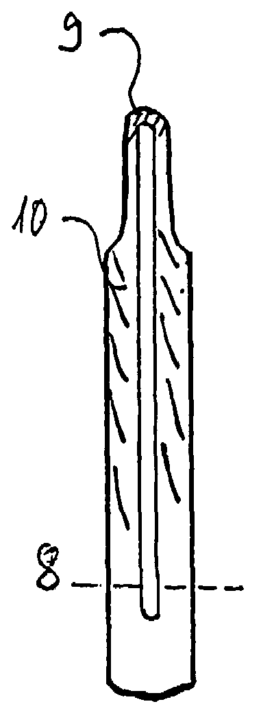
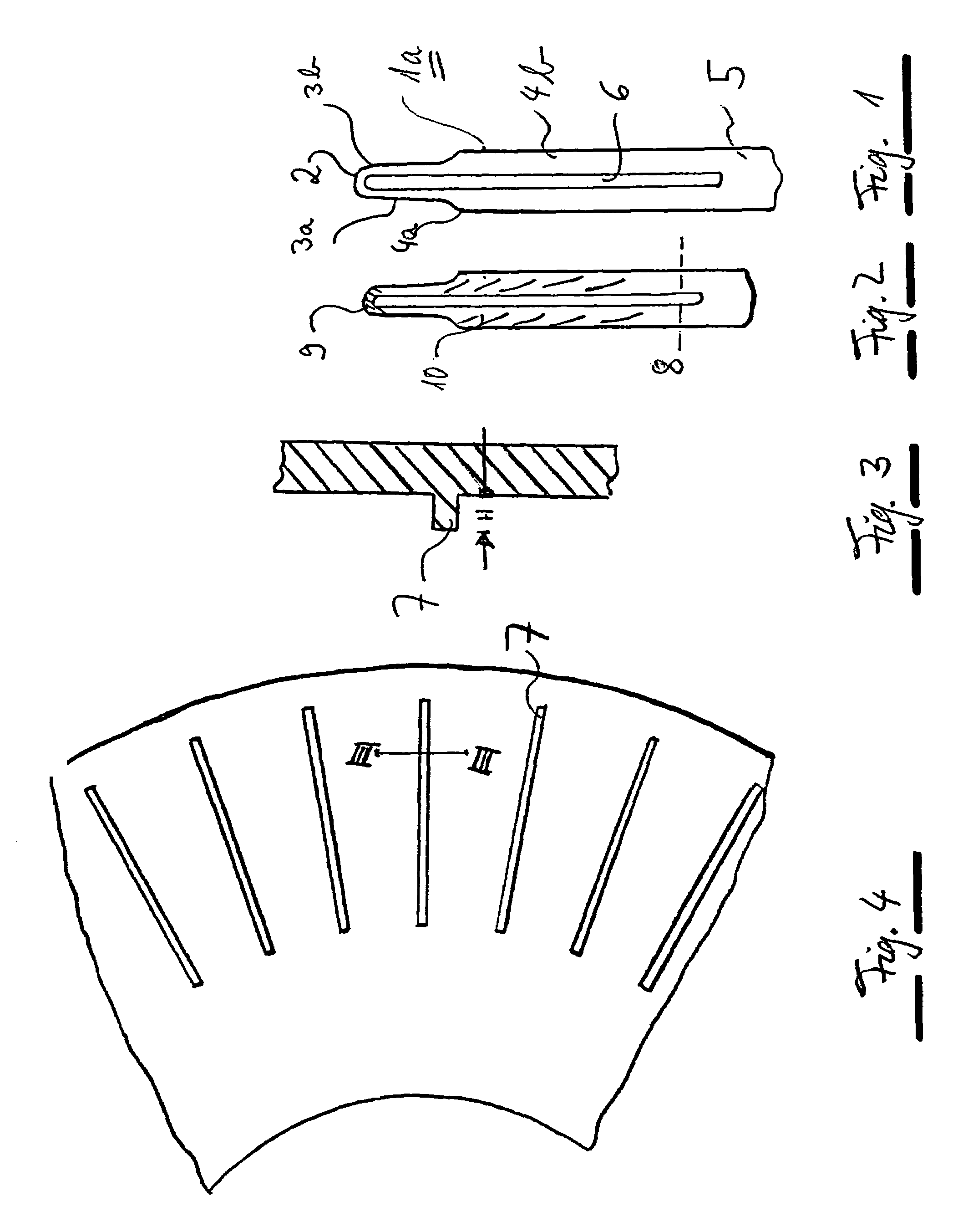
[0028]FIG. 1 shows an initial blank made of silicon carbide ceramic, which may be produced, for example, according to the method described in German Patent No. 42 33 626. In this context, however, deviating from the method described there, a silicon carbide starting material is used which has a low proportion of aluminum doping.

[0029]The slip produced from the aluminum-containing silicon carbide starting material is formed into an initial blank 1a. This initial blank 1a has a rounded tip 2 which is connected via two thin shanks 3a, 3b to a base element made of wider shanks 4a, 4b. The two shanks 4a, 4b are connected to each other in a region 5 at the opposite end of tip 2. A wide slot 6 extends between shanks 4a, 4b, 3a, 3b from tip 2 to lower connecting region 5.

[0030]In a practical exemplary embodiment, the initial blank has a thickness of about 1.5 mm and a length of about 65 mm.

[0031]The silicon carbide blank of FIG. 1 is mounted upon a round carrier made of graphite which has s...


PUM

PropertyMeasurementUnit
Temperatureaaaaaaaaaa
Fractionaaaaaaaaaa

Abstract

A ceramic heating element arrangement in which a ceramic heating element made of SiC having electrical NTC (negative temperature coefficient) properties is provided for a circuit. At least one segment is provided in the circuit, whose resistance saturates at least quasi-asymptotically at the current flow required for a desired heat development.

Description

FIELD OF THE INVENTION[0001]The present invention relates to a ceramic heating element and to a method for its production.BACKGROUND INFORMATION[0002]Ceramic heating elements can be used, for instance, in the case of burners, for heating a mixture to be combusted to a temperature above the ignition temperature. Such ceramic heating elements made of silicon carbide may be produced in different ways. Frequently, the silicon carbide elements are not very dense but large-pored, which leads to a low mechanical loadability.[0003]U.S. Pat. No. 5,322,824 describes a silicon carbide ceramic composite article that is sintered without the use of pressure, and has a direct current conductivity of at least 0.05 (ohm×cm)−1, a volume density of at least 2.9 g / cm3, a bending strength of at least 100 Mpa. The composite article has conductivity properties of the p type, and includes approximately 0.5 through 6.0 weight % of aluminum and 0.1 through 2.0 weight % of boron being admixed, the aluminum be...

Claims


Application Information

Patent Timeline
IPC IPC(8): F23Q7/00H05B1/02C04B35/565F23Q7/22H01C7/04H01C7/06H05B3/14
CPCC04B35/565F23Q7/22H01C7/048H05B3/148H01C7/06Y10T29/49083H05B2203/019
Inventor HEUBERGER, MARTINKUNTZ, MICHAELNASS, RUDIGER
Owner HEUBERGER MARTIN
Learn More