
High pressure superabrasive particle synthesis

a superabrasive particle and high-pressure technology, applied in the direction of crystal growth process, earth drilling and mining, chemical/physical processes, etc., can solve the problems of difficult to grow saw diamond grits, difficult to maintain optimal pressure and temperature conditions for homogeneous growth of diamond grits, and few companies are capable of growing high-grade saw grits having larger sizes, so as to reduce the quality of the final grown diamond

Inactive Publication Date: 2008-01-29
SUNG CHIEN MIN
View PDF37 Cites 32 Cited by
  • Summary
  • Abstract
  • Description
  • Claims
  • Application Information

AI Technical Summary

Benefits of technology

This approach results in high-quality diamond particles with a narrow size distribution and increased yield, achieving up to 80% conversion of carbon to diamond with 50-90% being of high quality, and significantly fewer inclusions compared to conventional methods.

Problems solved by technology

Hence, it is very difficult to maintain optimal conditions of pressure and temperature for homogeneous growth of diamond grits.
Consequently, saw diamond grits are very difficult to grow, particularly those having high quality.
These difficulties partially account for the abundance of companies which can grow saw grits, while very few companies are capable of growing high grade saw grits having larger sizes.
Unfortunately, typical processes also result in the crystals having external flaws, e.g., rough surfaces, and undesirable inclusions, e.g., metal and carbon inclusions.
Therefore, increased costs are incurred in segregating acceptable high strength diamonds from weaker, poor quality diamonds.
Random nucleation methods typically allow some regions of raw materials to be wasted while other regions are densely packed with diamond crystals having a high percentage of defects.
Some diamond synthesis methods have improved nucleation uniformity somewhat; however, during diamond growth local changes in pressure can occur.
If heating is accomplished by passing electrical current directly through the reaction cell, then diamond growth can also interfere with the electrical current used to control heating.
The results of such interference are non-uniformities and fluctuations in the temperature and pressure gradients across the reaction cell and thus a wide distribution of crystal sizes, crystal shapes, and inclusion levels.
This marginal yield still wastes large amounts of raw materials, reduces production efficiencies, and leaves considerable room for improvement.
However, such materials are intrinsically heterogeneous.
However, powdered mixture methods can be difficult to control.
For example, the density of graphite and metal catalyst materials differ significantly, making uniform mixing very difficult.
In addition, powdered mixture methods generally require even more strict control of process conditions than in layered methods.

Method used


Image

  • High pressure superabrasive particle synthesis
  • High pressure superabrasive particle synthesis
  • High pressure superabrasive particle synthesis

Examples


example 1

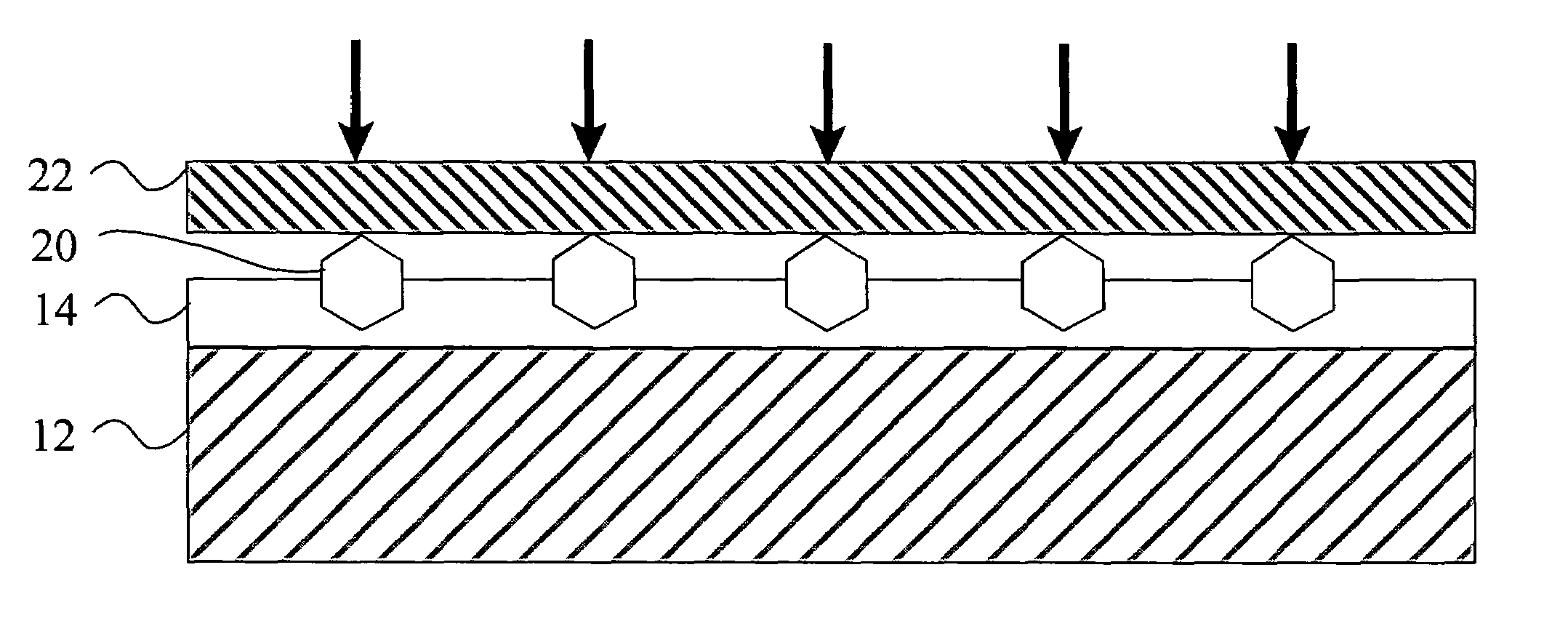
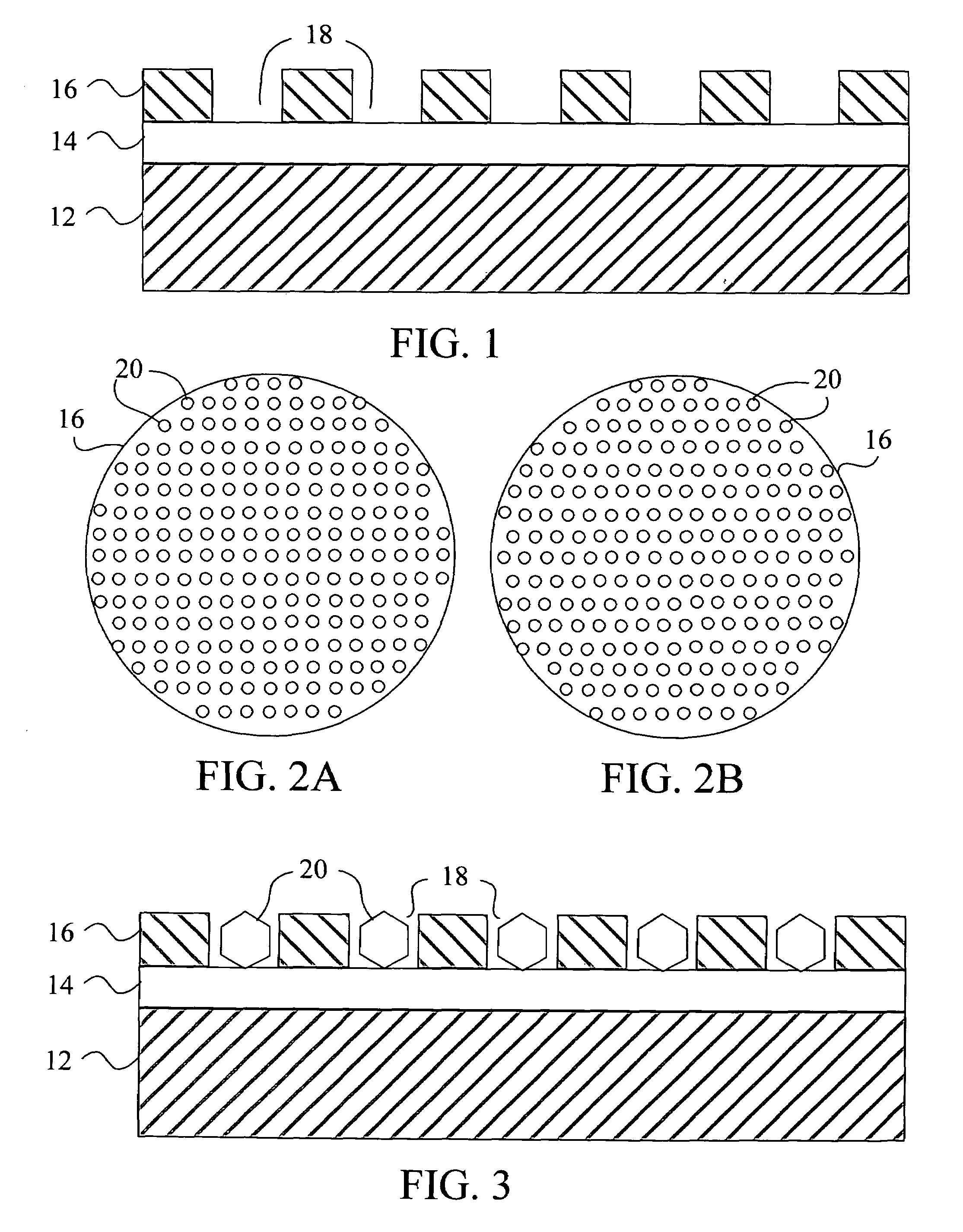
[0089]A circular mold having a diameter of 46 mm was filled with powdered natural graphite having a mesh size of about 20 μm, low resistivity of about 5 μΩ, and a degree of graphitization of 0.8. The graphite was purified to be substantially free of oil, organic binders, ash, or other non-carbon materials. The graphite was cold pressed at 150 MPa to form a particulate compact disk having a thickness of 0.7 mm and a density of 2 g / cm3 (12% porosity). High purity INVAR (Fe-35Ni with a mesh size of less than 40 μm) was placed on top of the graphite layer and cold pressed at 150 MPa to form a particulate catalyst layer having a thickness of 0.2 mm and a density of 6 g / cm3 (less than 33% porosity). A template similar to that shown in FIG. 2B, having apertures spaced 0.8 mm apart (center-to-center) and apertures 130 μm in diameter was placed on the catalyst layer. The template was covered in uncoated diamond seeds having a mesh size of 120 / 140 (about 115 μm in diameter) such that the aper...

example 2

[0090]A circular mold having a diameter of 46 mm was filled with powdered natural graphite having a mesh size of about 20 μm, low resistivity of about 5 μΩ, and a degree of graphitization of 0.8. The graphite was purified to be substantially free of oil, organic binders, ash, or other non-carbon materials. The graphite was mixed with high purity INVAR (Fe-35Ni with a mesh size of less than 40 μm). The weight ratio of graphite to metal catalyst was 1:1.5. The mixture was then cold pressed at 250 MPa to form a particulate compact disk having a thickness of 0.7 mm and a density of 2 g / cm3 (12% porosity). A template similar to that shown in FIG. 2B, having apertures spaced 0.8 mm apart (center-to-center) and apertures 130 μm in diameter was placed on the compact disk. The template was covered in uncoated diamond seeds having a mesh size of 120 / 140 (about 115 μm in diameter) such that the apertures were filled. The excess diamond seeds were then collected for reuse. The template was remo...

example 3

[0091]Graphite disks were prepared by pressing natural graphite powder having a grain size of about 20 microns into disks 37 mm in diameter and 0.8 mm in thickness at about 400 MPa. The porosity of the resulting graphite disks was about 15%. Ni coated diamond seeds (precoated diameter of about 65-75 microns) having a coated diameter of about 105-125 microns were planted into the graphite disks in a grid pattern having a pitch of about 0.8 mm to form seeded graphite disks. The seeded graphite disks were alternated with INVAR (Fe65-Ni35) disks and loaded into a steel container to make a final growth cell of 38.8 mm in diameter and 30 mm in height. One hundred of these growth cells were pressed in a 2500 ton cubic press with a ram size of 600 mm to attain a pressure of about 5.2 GPa and temperature of about 1250° C. The pressure and temperature were maintained for 50 minutes and then the pressure was reduced and the temperature gradually decreased. The pressed growth cells were broken ...


PUM

PropertyMeasurementUnit
particle sizeaaaaaaaaaa
volumesaaaaaaaaaa
degree of graphitizationaaaaaaaaaa

Abstract

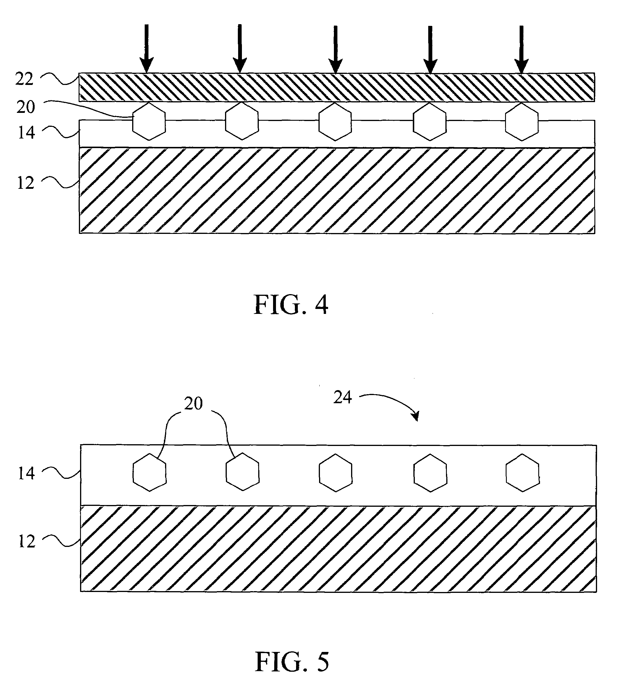
An improved method for controlling nucleation sites during superabrasive particle synthesis can provide high quality industrial superabrasive particles with high yield and a narrow size distribution. The synthesis method can include forming a raw material layer, forming a particulate catalyst layer adjacent the raw material layer, and placing crystalline seeds in a predetermined pattern at least partially in the catalyst layer or raw material layer to form a growth precursor. Alternatively, the raw material and catalyst material can be mixed to form a particulate crystal growth layer and then placing the crystalline seeds in a predetermined pattern in the growth layer. Preferably, seeds can be substantially surrounded by catalyst material. The growth precursor can be maintained at a temperature and pressure at which the superabrasive crystal is thermodynamically stable for a time sufficient for a desired degree of growth. The crystalline seeds can be placed in a predetermined pattern using a template, a transfer sheet, vacuum chuck or similar techniques. The superabrasive particles grown using the described methods typically have a high yield of high quality industrial particles and a narrow distribution of particle sizes.

Description

PRIORITY INFORMATION[0001]This application is a continuation-in-part of U.S. patent application Ser. No. 10 / 259,168, filed Sep. 27, 2002, now U.S. Pat. No. 7,124,753, which is a continuation-in-part of U.S. patent application Ser. No. 09 / 935,204, filed Aug. 22, 2001, now issued as U.S. Pat. No. 6,679,243, which is a continuation-in-part of U.S. patent application Ser. No. 09 / 399,573, filed Sep. 20, 1999, now issued as U.S. Pat. No. 6,286,498, which is a continuation-in-part of U.S. patent application Ser. No. 08 / 832,852, filed Apr. 4, 1997, now abandoned, all of which are incorporated herein by reference.FIELD OF THE INVENTION[0002]The present invention relates generally to methods of synthesizing superabrasive particles, wherein crystalline seeds can be arranged in a predetermined pattern. Accordingly, the present invention involves the fields of chemistry, metallurgy, and materials science.BACKGROUND OF THE INVENTION[0003]Diamond and cubic boron nitride (cBN) particles have found ...

Claims


Application Information

Patent Timeline
Patent Type & Authority Patents(United States)
IPC IPC(8): B28D1/02B24D11/00C30B29/04B01J3/06B23D61/18B23D65/00B23P15/28B24D3/08B24D7/06B24D18/00B24D99/00C22C1/05C22C26/00C30B29/64E21B10/56E21B10/567
CPCB01J3/062B23D61/18B23D65/00B23P15/28B24D3/08B24D7/066B24D18/00B24D99/005C22C1/051C22C26/00E21B10/5676B22F1/0011B22F3/004B01J2203/061B01J2203/062B01J2203/0635B01J2203/0645B01J2203/0655B01J2203/066B01J2203/068B01J2203/0685B22F2005/001B22F2999/00C22C2204/00B22F2207/03B22F2003/1046B24D2203/00B22F1/05
Inventor SUNG, CHIEN-MIN
Owner SUNG CHIEN MIN
Learn More