
Transmitter, SONET/SDH transmitter, and transmission system

a transmission system and transmitter technology, applied in the field of transmitters, sonet/sdh transmitters, and transmission systems, can solve the problems of not being suitable for star-configured networks, affecting and it takes a few seconds to a few minutes for the transmission line to be recovered, so as to achieve fast processing, reduce the size of circuitry, and enhance the stability of the switching in the network

Inactive Publication Date: 2008-01-01
FUJITSU LTD
View PDF15 Cites 79 Cited by
  • Summary
  • Abstract
  • Description
  • Claims
  • Application Information

AI Technical Summary

Benefits of technology

[0071]With this arrangement, by employing the transmission line (PT) when a fault occurs at the transmission line (WK), packet loss due to a transmission line fault and a transmitter failure can be minimized. In this manner, stable operation of the network becomes possible. In addition, during maintenance, an inspection can be conducted without disconnecting communication.
[0089](15) Each of the transmitters may be point-to-point connected with the transmitter opposite. Each transmitter may be constructed so that it can transfer a specific packet containing transmission-line switching information about the transmission lines. In this case, the number of line protection structures is increased and stability in the network is further enhanced.

Problems solved by technology

Furthermore, if optical fibers, etc., are physically cut, it will take a few seconds to a few minutes for the transmission line to be recovered.
If a fault occurs at an optical fiber connected to an IP router near a core system, the influence of the line disconnection will be considerable.
The SRP is applied to LAN systems and supports only ring-configured networks and is not suitable for star-configured networks that are employed mainly in Ethernet.
In addition, it takes a few seconds for a working router to be switched from the occurrence of a fault.
On the other hand, changing the existing network structures to add the function of healing a fault when it occurs is not practical due to interruption of service, an increase in cost, etc.
In addition, because the routing protocol by IP routers changes a route by a protocol level between routers, the time required for line recovery is considerable (typically on the order of a minute or second).
Moreover, since there is a need to overwrite information (routing table) about the routes of the whole network, there is still a problem that it will take time for a fault to be completely recovered.
Thus, when traffic is heavy, there is a problem that transmission service cannot be offered to users with high reliability.

Method used


Image

  • Transmitter, SONET/SDH transmitter, and transmission system
  • Transmitter, SONET/SDH transmitter, and transmission system
  • Transmitter, SONET/SDH transmitter, and transmission system

Examples


first embodiment

(A) First Embodiment

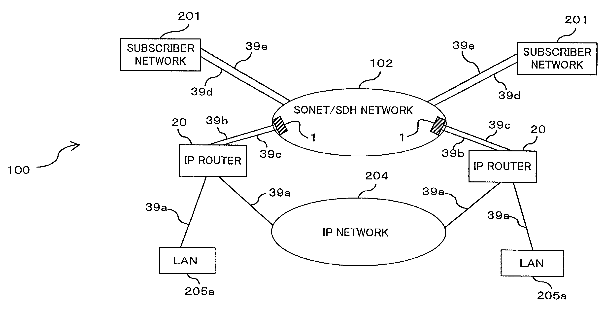
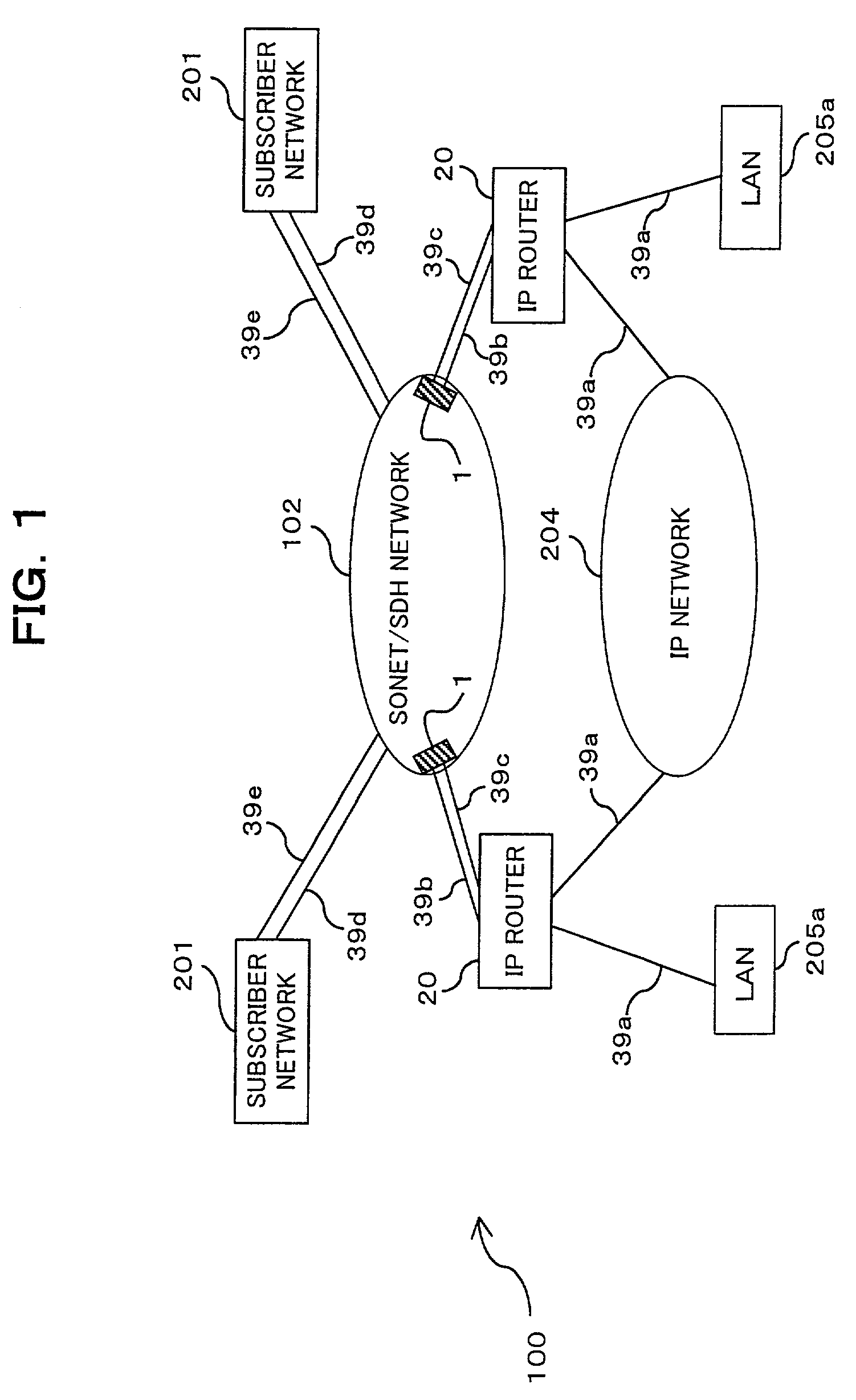
[0143]FIG. 1 schematically shows a transmission system according to a first embodiment of the present invention. The transmission system 100 shown in the figure transmits and receives a packetized transmission signal and is equipped with IP routers 20, SONET / SDH apparatus (SONET / SDH transmitters with 1 Gbps / 10 Gbps Ethernet interfaces) 1, transmission lines (packet transmission lines) 39a to 39c, optical transmission lines 39d, 39e, an IP network (Internet) 204, LANs 205a, subscriber networks 201, and a SONET / SDH network 102.

[0144]The transmission system 100 relates primarily to a communication method between the SONET / SDH apparatus 1 and the IP router 20, and transmitters employing the communication method. The IP router 20 and the SONET / SDH apparatus 1 both function as transmitters. Note that the SONET / SDH apparatus 1 may have either a 1 Gbps Ethernet interface or a 10 Gbps Ethernet interface.

[0145]The SONET / SDH apparatus 1 has the function of transmitting and ...

second embodiment

(B) Second Embodiment

[0400]A transmission system in the second embodiment can be realized by attaching a transmitter (automatic protection switching (APS) adapter), which has the function of switching WK and PT, to the outside of an IP router already provided in a network.

[0401](7) System Constitution

[0402]In the transmission system according to the second embodiment, transmitters constituting the transmission system have the APS function of switching WK and PT by employing a K-packet.

[0403](7-1) Transmission System 100a

[0404]FIG. 23 schematically shows the transmission system 100a according to the second embodiment of the present invention. The transmission system 100a shown in the figure is constructed so that between an IP network 204 and a SONET / SDH network 102, IP routers 203, APS adapters 15, and a SONET / SDH transmitter (with 1 Gbps / 10 Gbps Ethernet) 30 are connected via Ethernet. Other than these, parts with the same reference numerals as the aforementioned parts have the sa...


PUM


Abstract

Disclosed herein is a SONET / SDH transmitter provided in a transmission system in which a SONET / SDH network and an IP network are connected with optical LAN-IF. The SONET / SDH transmitter has a redundancy transmission line structure consisting of two transmission lines, a K-packet processing section, and a transmitting section. The K-packet processing section is used for generating a specific byte (SONET K1 / K2 byte) of data representing transmission-line switching control information about the transmission lines, packetizing the generated data, and outputting a packet. The transmitting section is used for transmitting the packet to the transmitter provided opposite through the transmission lines. This SONET / SDH transmitter further has a redundancy line switching section. The redundancy line switching section is capable of selecting a transmission line, where a transmission signal with information data is transmitted, according to a status in which a packetized specific byte of data from the transmitter opposite is received.

Description

BACKGROUND OF THE INVENTION[0001](1) Field of the Invention[0002]The present invention relates generally to the interface between an Internet protocol (IP) network and a synchronous optical network / synchronous digital hierarchy (SONET / SDH) network, and more particularly to a transmitter, a SONET / SDH transmitter, and a transmission system suitable for line protection meeting Ethernet of 1 Gbit / sec and 10 Gbit / sec.[0003](2) Description of the Related Art[0004]Recently, with the demand for the higher-speed operation of a local area network (LAN), the standard of 1 Gbit / sec Ethernet (hereinafter referred to as 1 Gbps Ethernet or 1 GbE) has spread, and a high-speed LAN optical interface called 10 Gbit / sec Ethernet (hereinafter referred to as 10 Gbps Ethernet or 10 GbE) has been examined as the next generation LAN standard.[0005]In the IP network, a voice over Internet protocol (hereinafter referred to as a VoIP) for transmitting voice by employing IP packets (IP datagrams) is also being ...

Claims


Application Information

Patent Timeline
Patent Type & Authority Patents(United States)
IPC IPC(8): G01R31/08H04J3/14H04J3/16H04J3/00H04L45/24H04L45/243H04L45/247H04Q11/04
CPCH04J3/14H04J3/1611H04L45/586H04J2203/006H04J2203/0082H04J2203/0085
Inventor MORITA, HIROTAKATAKAGI, YOSHINOBUMIYASHITA, TAKUYAKOMATSU, CHIYOKO
Owner FUJITSU LTD
Learn More