
Foot-controlled motorized vehicle

Inactive Publication Date: 2007-11-13
SPITAL WADE
View PDF8 Cites 49 Cited by
  • Summary
  • Abstract
  • Description
  • Claims
  • Application Information

AI Technical Summary

Benefits of technology

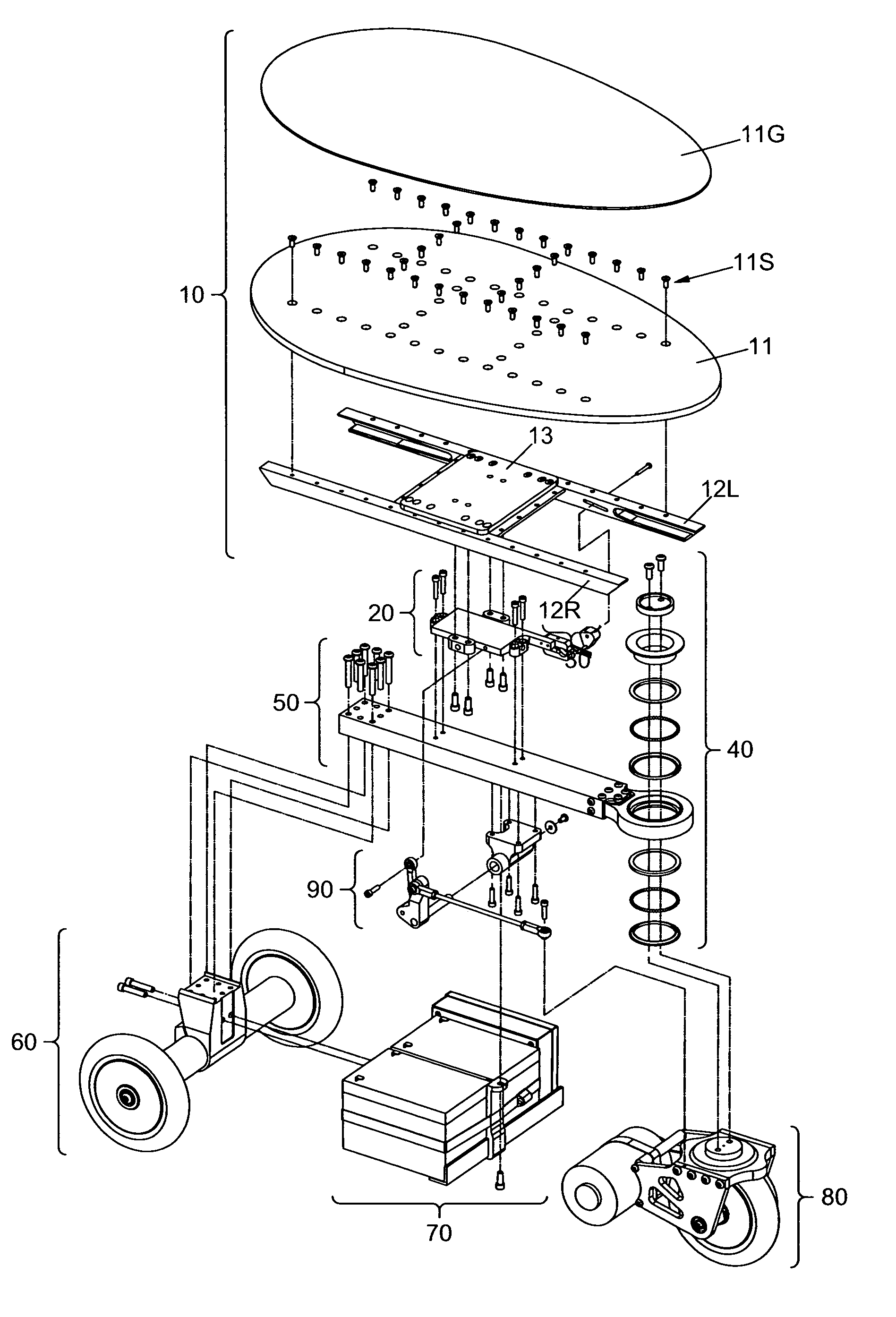
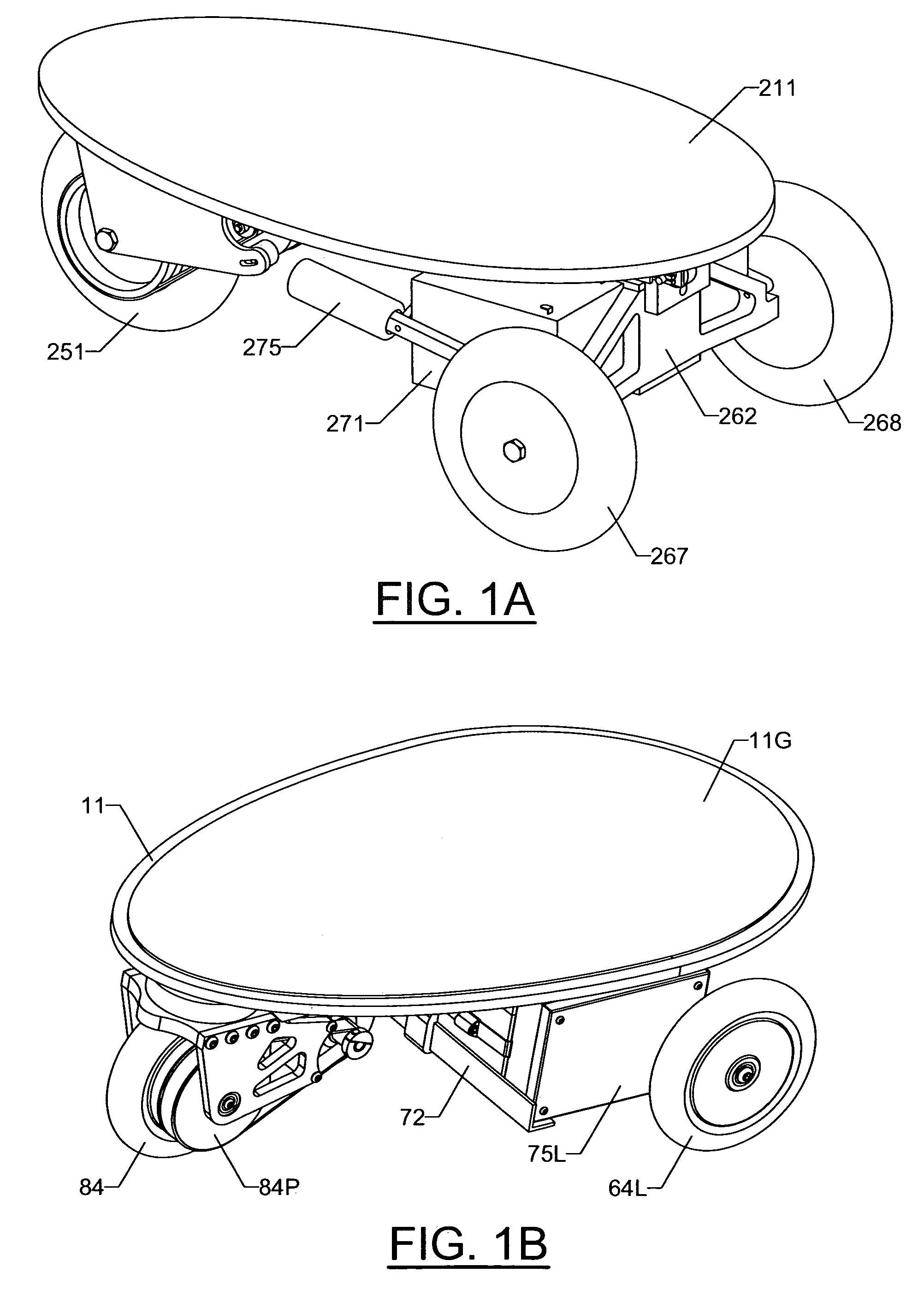
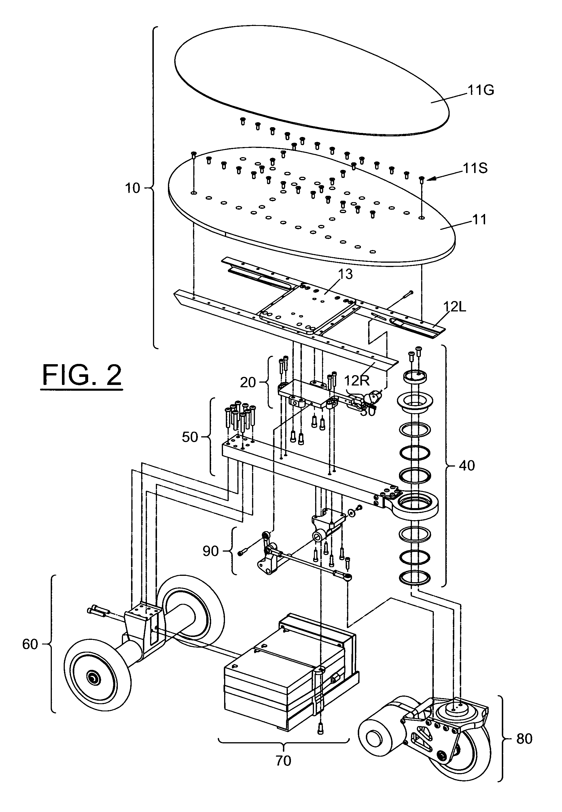
[0030](c) to provide a foot-controlled motorized vehicle that allows the rider to place one foot substantially in front of the other whether accelerating or decelerating the vehicle. This will allow the rider to maintain stability and balance during all phases of the vehicle's operation.(d) to provide vehicle with a rider-supporting platform upon which a rider may stand, sit or kneel. The vehicle will be entirely controllable by the shifting of the rider's weight upon the rider-supporting platform. This will provide an alternative to standing while riding the vehicle. Some will find sitting or kneeling easier and more enjoyable. Sitting or kneeling can also be a way to learn to ride the vehicle. Some may want to practice in this manner and then try standing up.(e) to provide a foot-controlled motorized vehicle that can negotiate a wide variety of adverse terrains and riding conditions. This will make the vehicle versatile and useful in a broad range of situations and places.(f) to provide an embodiment of this vehicle that can be accelerated or decelerated in either the forward or reverse direction. Once again, the rider will be able to perform these actions without hand controls and without repositioning either foot. The ability to reverse directions will make the vehicle more dexterous, maneuverable and enjoyable to ride.(g) to provide an embodiment with only three wheels. This will simplify its manufacture and help to differentiate it from other vehicles on the market.(h) to provide a simple drive system. The embodiments shown utilize a single front wheel to both power and steer the vehicle. The single front wheel and the drive motor are both mounted to a steerable truck. Power is transmitted by a simple timing belt from the motor to the front wheel. This eliminates the need for a flexible coupling such as a U-joint or a constant-velocity joint. A flexible coupling like this would otherwise be required to transmit power from a chassis-mounted motor to a steerable drive wheel.(i) to provide a drive system with no need for a differential. A differential is generally required on vehicles which employ laterally paired drive wheels. This is because laterally paired drive wheels must be allowed to rotate at different speeds when the vehicle is turning. A car is a good example of this. When a car goes around a turn, it's differential allows the outer wheel to spin faster than the inner wheel. The one-wheel drive system provided eliminates the need for such a differential.(j) to provide an embodiment of this invention that has a unique visual appeal. The look of this vehicle will provide a significant marketing advantage. The embodiments shown feature an egg-shaped deck. This egg-shaped deck complements the vehicle's three wheel design and helps differentiate it from other skateboards and scooters.(k) to provide an embodiment of this invention that it can be powered by an internal combustion engine or an electric motor. This will give the developer greater flexibility in providing a power source for the vehicle.

Problems solved by technology

The popularity of skateboards, however, has been limited in part because they are difficult to ride.
Propelling a skateboard requires significant balance and coordination.
It follows that skateboards have not been attractive to non-risk takers or those who feel they might be somewhat uncoordinated.
Skateboards also do not have their own power source, making them unsuitable for non-athletic people or those in dressy or business attire.
Furthermore, the small, hard wheels on skateboards make them very difficult to ride on rough or rocky surfaces and largely unsuitable for unpaved surfaces.
Although not as easy to carry or store as a skateboard, they can be folded when not being ridden.
Kick scooters, however, are not powered and have enjoyed little popularity among teens and adults.
Go-peds tend to be faster than the electric versions, but they also create more noise.
While motorized kick scooters have enjoyed some popularity, they lack some of the advantages of skateboards.
They are larger and more difficult to carry and store.
They also cannot be ridden hands-free as a skateboard can.

Method used


Image

  • Foot-controlled motorized vehicle
  • Foot-controlled motorized vehicle
  • Foot-controlled motorized vehicle

Examples


first embodiment

Operation of First Embodiment

Overview of Acceleration and Deceleration (FIGS. 6A-6F)

[0080]In its resting position Deck 11 is approximately parallel to the ground and the vehicle moves neither forward nor backward. Acceleration, deceleration and reversal of the vehicle's direction are controlled by tilting Deck 11 either forward or backward. When the rider's weight is shifted forward over the front foot, Deck 11 tilts forward and the vehicle accelerates in that direction. When more weight is shifted to the rear foot, Deck 11 tilts backward and the vehicle accelerates in that direction. Acceleration and deceleration are variable so the vehicle responds in proportion to the amount of weight change.

Details of Acceleration and Deceleration

[0081]Deck 11 tilts forward or backward at the pivotal connection created by Throttle Pivots 14L &14R (FIG. 3) and Throttle Pivot Pins 22L &22R (FIG. 5A). As Deck 11 is tilted forward or backward, Throttle Pin 35 moves up or down causing a corresponding...

second embodiment

Operation of Second Embodiment

[0090]From the rider's standpoint, the second embodiment operates generally like the first embodiment. Please refer to FIGS. 6A-6F, FIGS. 7A-7F, and the “OPERATION OF FIRST EMBODIMENT” section above for a general understanding of this vehicle's operation.

Acceleration and Deceleration

[0091]Deck 211 may tilt either forward or backward in response to the rider's forward or backward weight placement (FIG. 8A). This tilting occurs because the Deck's substructure, Deck Bars 212&213 pivot upon Throttle Pivot Pin 223. The tilting causes Throttle Actuator Pin 233 to move up and down (FIG. 8B). The Actuator Pin pushes against the inside walls of the slot in Throttle Finger 232. This causes the wiper shaft on Throttle Potentiometer 231 to turn. Throttle Potentiometer 231 is connected to the motor speed controller (not shown) which is in turn connected to, and controls the speed and direction of, Motor 254 (FIG. 9A). The shaft of Motor 254 turns Front Wheel 251 bec...


PUM


Abstract

A weight-controlled, motorized vehicle can be accelerated in either direction, steered, or decelerated without hand controls and without repositioning of a rider situated atop the vehicle. Like a skateboard, the vehicle is normally ridden by a rider standing upon a platform on top of the vehicle with one foot in front of the other. The vehicle is propelled forward when the rider increases weight on the front portion of the platform and backward when weight is increased on the rear portion. The vehicle is steered like a skateboard, by tilting the platform from side-to-side. An improved drive system utilizes a single front drive wheel to power and steer the vehicle. The drive system eliminates need of a flexible power transmission coupling such as a U-joint or constant-velocity joint. It also eliminates need of the differential mechanism normally required for two laterally spaced drive wheels.

Description

CROSS-REFERENCE TO RELATED APPLICATIONS[0001]This invention claims benefit of PPA Ser. No. 60 / 442,367 filed Jan. 25, 2003FEDERALLY SPONSORED RESEARCH[0002]NONESEQUENCE LISTING[0003]NONEBACKGROUND OF THE INVENTION[0004]1. Field of Invention[0005]This invention relates to personal motorized vehicles, specifically to a motorized, skateboard-like vehicle whose speed and direction can be controlled entirely by the feet of its rider.[0006]2. Description of Prior ArtSkateboards[0007]Skateboards have enjoyed popularity in recent years for several reasons. One is that skateboards are relatively simple and inexpensive. Another is that a skateboard can be ridden hands-free which allows the rider's hands to do something else, like carry something. The skateboard's small size also permits it to be stored without difficulty and carried easily when it is not being ridden.[0008]The popularity of skateboards, however, has been limited in part because they are difficult to ride. Propelling a skateboa...

Claims


Application Information

Patent Timeline
IPC IPC(8): A63C17/12
CPCA63C17/12A63C17/01
Inventor SPITAL, WADE
Owner SPITAL WADE
Learn More