Electrophoretic apparatus and electronic equipment
a technology which is applied in the field of electrophoretic display device and electronic equipment, can solve the problems of difficult rewriting of display, easy improvement of compatibility of conventional electrophoretic display device, and difficulty in erasure, etc., and achieve excellent erasability and excellent memorization property
- Summary
- Abstract
- Description
- Claims
- Application Information
AI Technical Summary
Benefits of technology
Problems solved by technology
Method used
Image
Examples
example 1
[0173]An electrophoretic display panel was prepared by the following method, and a manufacturing process of the microcapsules will be described with reference to FIG. 13.
[0174]As shown in FIG. 13(A), 5.5 g of a gelatin powder (manufactured by Kanto Kagaku), 5.5 g of a gum Arabic powder (manufactured by Kanto Kagaku), and 60 g of were put in a 500 ml-beaker to dissolve these powders into the water.
[0175]As shown in FIG. 13(B), an electrophoretic suspension (prepared beforehand) is dropped into the resulting solution while the solution was agitated at a rotation speed of 250 rpm. After the dropping was completed, the rotation speed was increased to 1,300 rpm, and agitation was further performed for 1 hour.
[0176]This electrophoretic suspension was prepared by the following method. 50 g of TiO2 particles (electrophoretic particles) “CR-90” manufactured by ISHIHARA SANGYO KAISHA, Ltd., 2.3 g of a titanate (titanic acid salt)-based coupling agent “KR-TTS” manufactured by Ajinomoto Co., In...
example 2
[0186]Microcapsules prepared by the same method as that in Example 1 (except that the composition of the capsule film was changed to gelatin: gum Arabic=3:2), the silicone binder “POLON-MF-40” manufactured by Shin-Etsu Chemical Co., Ltd., and the acrylic binder “E272” manufactured by Mitsui Toatsu Chemicals, Inc., were mixed such that a final weight ratio after drying of microcapsule:silicone resin:acrylic resin=10:0.8:1.2 was achieved.
[0187]The resulting mixture was applied by coating to a PET film provided with pixel electrodes made of ITO (an ITO thin film patterned into the shape of pixels) to achieve a film thickness of 130 μm, followed by drying at 90° C. for 20 minutes. In this manner, a layer composed of microcapsules 5 and a binder 7 was formed on the surface of the PET film provided with the pixel electrodes.
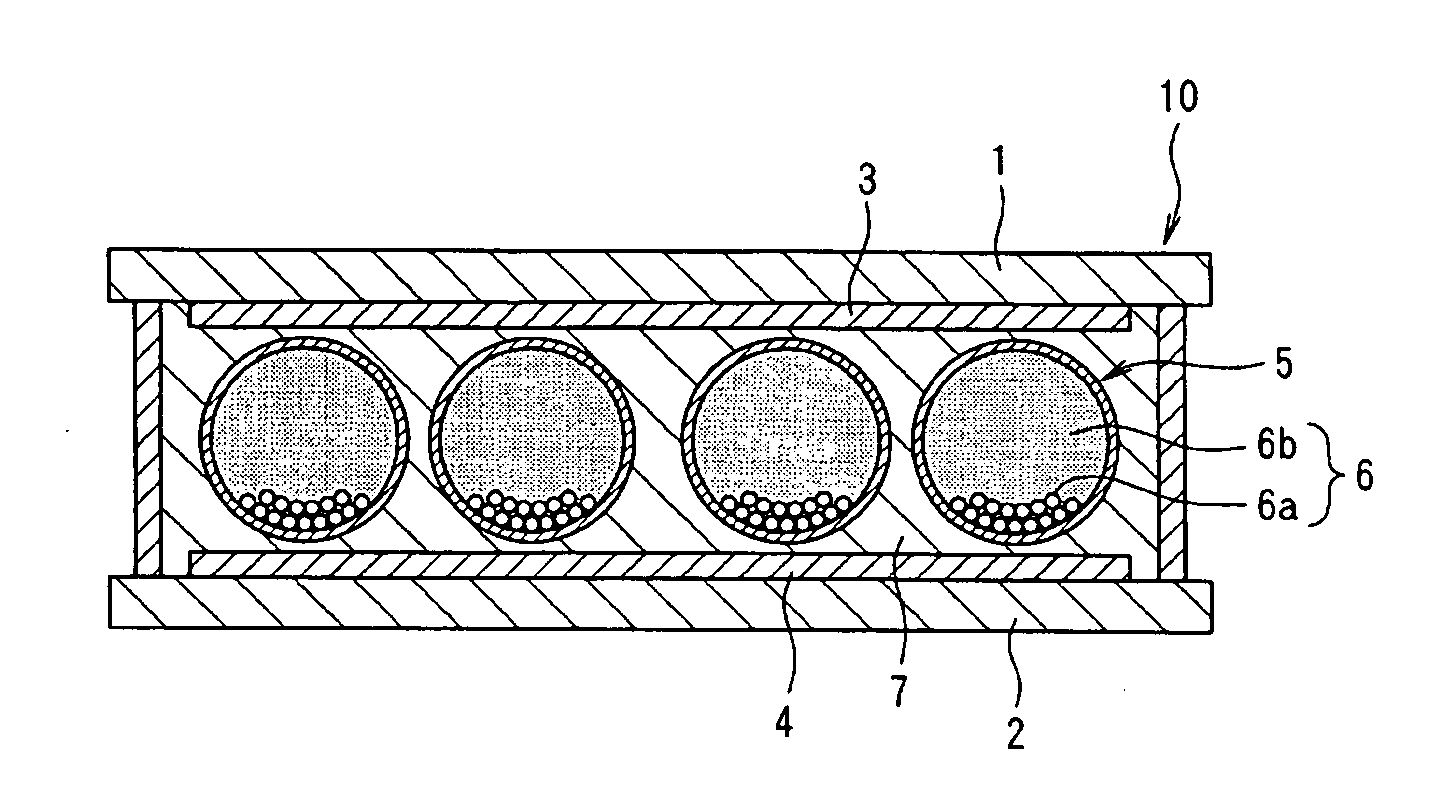
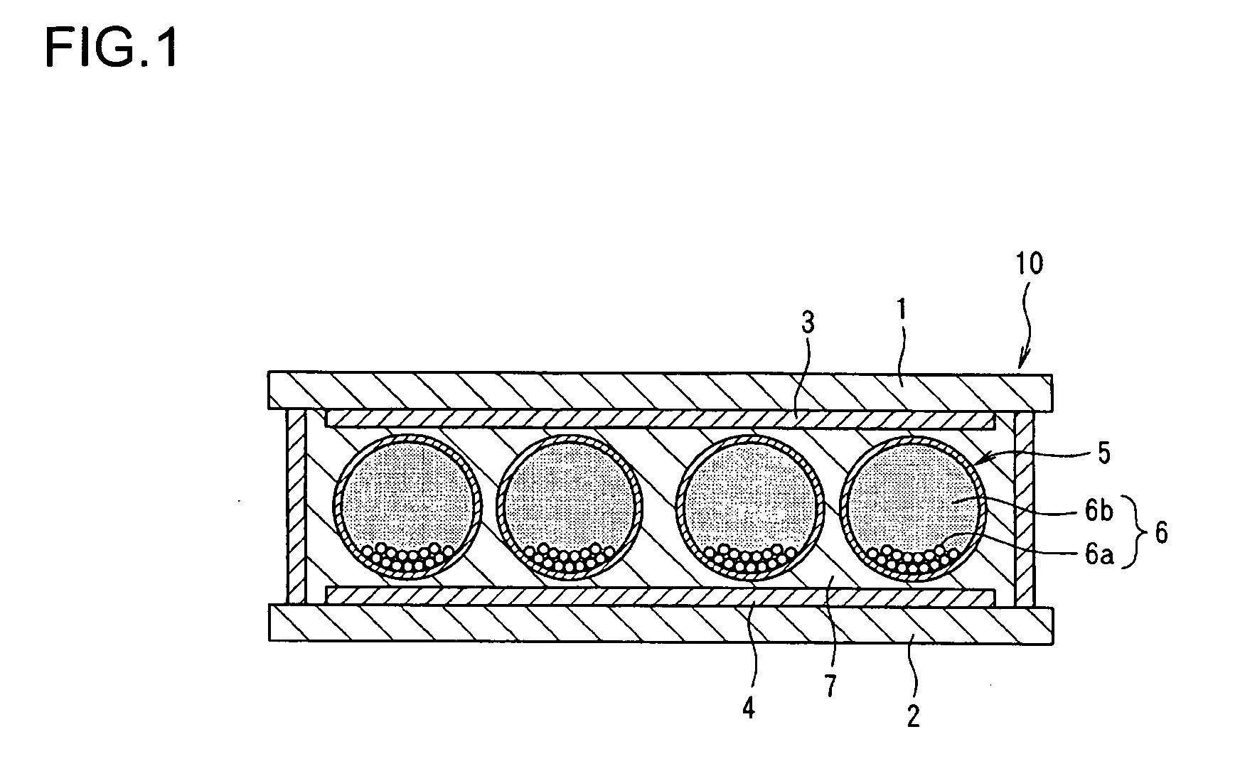
[0188]The steps following this were performed by the same method as that in Example 1, so that an electrophoretic display panel 10 was prepared, in which one pixel had...
example 3
[0190]An electrophoretic display panel was prepared by the same method as that in Example 1 except that an electrophoretic suspension was prepared by the following method.
[0191]The electrophoretic suspension was prepared by the following method. 50 g of TiO2 particles (electrophoretic particles) “CR-90” manufactured by ISHIHARA SANGYO KAISHA, Ltd., 50 g of black acrylic resin particles (electrophoretic particles) manufactured by Soken Chemical and Engineering Co., Ltd., 2.3 g of a titanate (titanic acid salt)-based coupling agent “KR-TTS” manufactured by Ajinomoto Co., Inc., 1 g of an aluminum-based coupling agent “AL-M” manufactured by Ajinomoto Co., Inc., and 300 g of dodecylbenzene (liquid phase dispersion medium) manufactured by Kanto Kagaku were put into a 500 ml-flask, followed by agitation while ultrasonic vibration was applied.
[0192]In this manner, an electrophoretic suspension was prepared, in which white TiO2 particles were dispersed in dodecylbenzene, while being negative...
PUM
| Property | Measurement | Unit |
|---|---|---|
| particle diameters | aaaaa | aaaaa |
| thickness | aaaaa | aaaaa |
| thickness | aaaaa | aaaaa |
Abstract
Description
Claims
Application Information
 - R&D Engineer
- R&D Manager
- IP Professional
- Industry Leading Data Capabilities
- Powerful AI technology
- Patent DNA Extraction
Browse by: Latest US Patents, China's latest patents, Technical Efficacy Thesaurus, Application Domain, Technology Topic, Popular Technical Reports.
© 2024 PatSnap. All rights reserved.Legal|Privacy policy|Modern Slavery Act Transparency Statement|Sitemap|About US| Contact US: help@patsnap.com


