
System and method for imaging sub-surface polarization-sensitive material structures

a subsurface polarization and material structure technology, applied in the field of imaging systems, can solve the problems of insufficient sensitivity and specificity of immunologic tests for high confidence in endometriosis diagnosis, lack of spatial resolution of ultrasound for detection of all but the largest lesions, and insufficient diagnostic techniques. , to achieve the effect of enhancing the directionality of these structures and underlying blood vessels, lightening intensity, and increasing backscattering

Inactive Publication Date: 2007-10-30
WALSH JR JOSEPH T +1
View PDF2 Cites 86 Cited by
  • Summary
  • Abstract
  • Description
  • Claims
  • Application Information

AI Technical Summary

Benefits of technology

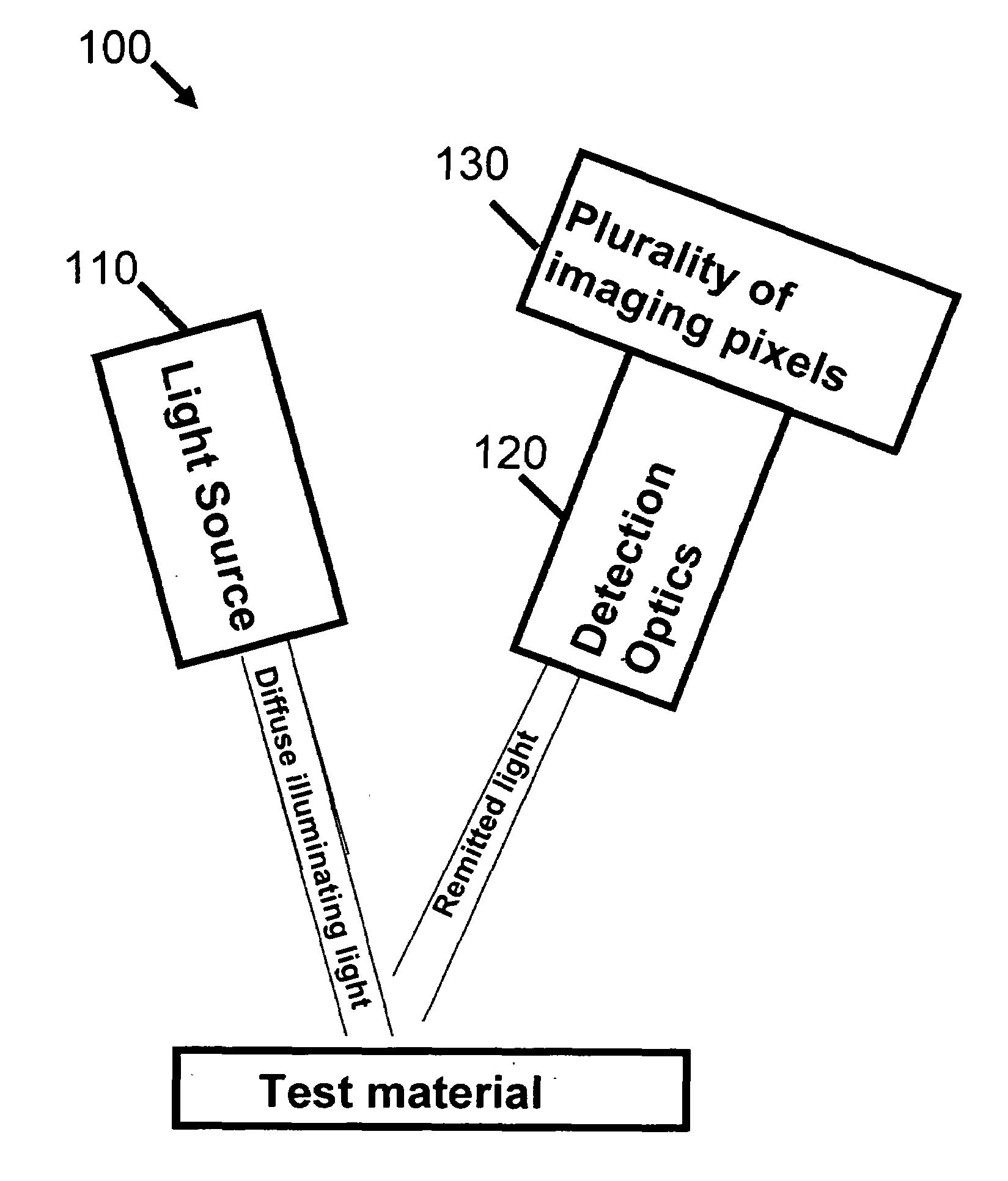
[0023]The present method and associated imaging apparatus take advantage of two key concepts in tissue optics: the polarization properties of remitted light used as a discriminating factor and radiation that penetrates the tissue sufficiently to image the structures of interest. The present system and method is preferably adjustable to accommodate the polarization properties of tissue structures, thereby allowing visualization of the differences that exist between the tissue matrix of the lesions and the surrounding normal tissue.
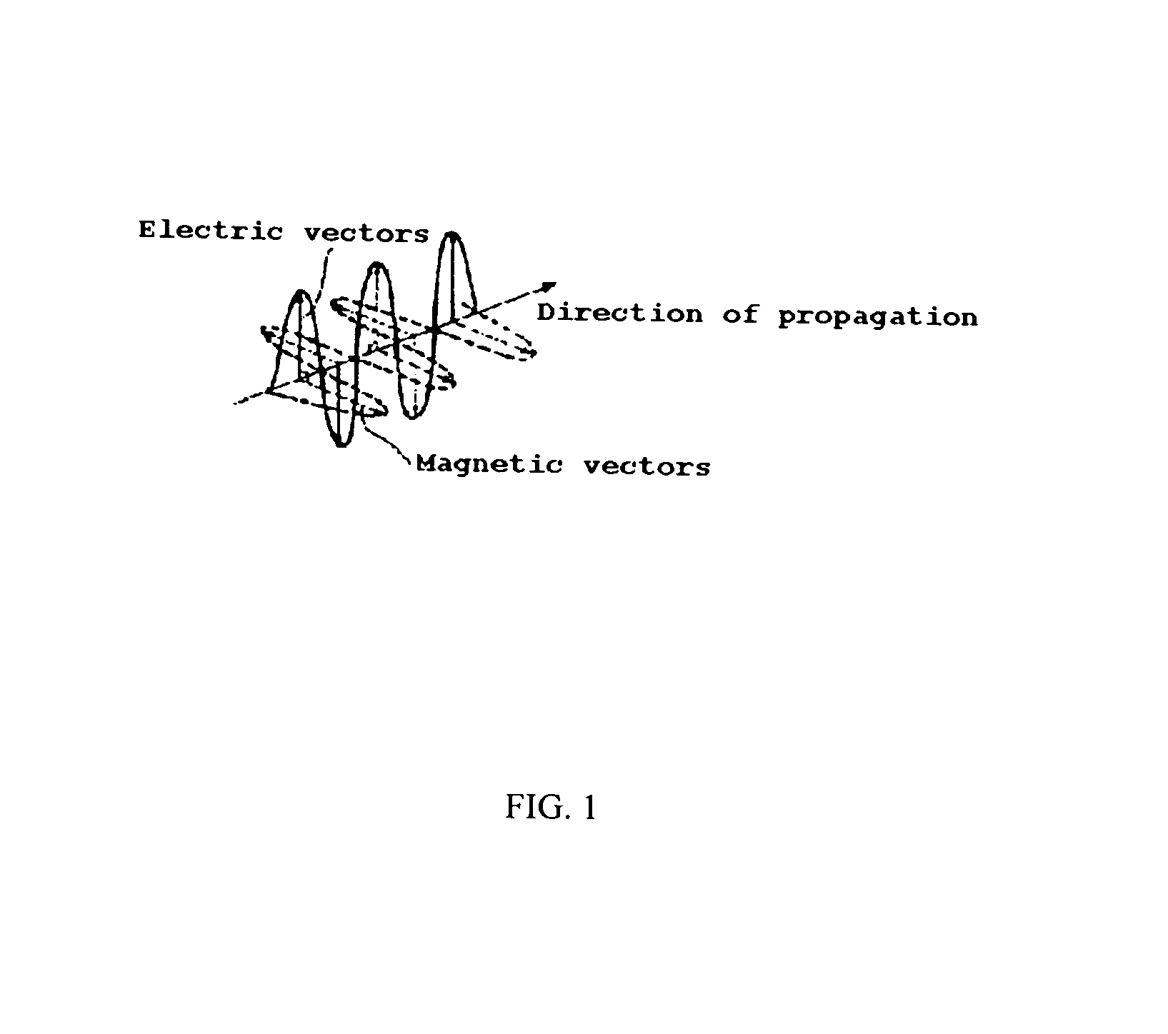
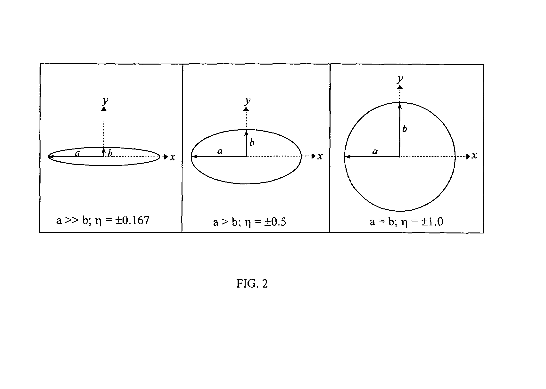
[0032]Stokes polarimetry imaging of internal collagenous-based tissues reveals details about tissue structure that are different from those revealed by unpolarized light imaging. Using unpolarized light imaging, the tissues appear rather uniform in texture and color except for the vessels which run throughout the tissue. Using unpolarized near-infrared light, denser tissues (i.e. blood vessels, fat, and muscular abdominal wall) appear lighter in intensity because of the increased backscattering of the light while other less-dense tissues (i.e. peritoneum unattached to the abdominal wall) appear darker as there was less backscattering of light. Still, detailed tissue structural information is lacking in these unpolarized images. Using Stokes-polarimetry imaging, the collagenous fiber-bundle structure running laterally to each other could be visualized. The directionality of these structures and underlying blood vessels are enhanced in the polarization-based image-maps. Hence, the use of polarized light for illumination and in the detection scheme provides an improved approach to visualize sub-surface tissue structures.
[0033]One advantage is that large areas of tissue can be scanned to obtain useful structural information without excision or chemical processing.

Problems solved by technology

Current diagnostic techniques have been less adequate in diagnosing endometriosis, including immunologic tests and radiological imaging.
Immunologic tests presently lack the sensitivity and specificity for high confidence in endometriosis diagnosis.
Ultrasound has also been used to detect endometrial lesions; however, ultrasound lacks the spatial resolution for detection of all but the largest lesions.
However, MRI is a costly screening tool, and more importantly, the MR contrast between the normal tissue and endometrial lesions is insufficient for accurate diagnosis especially for small lesions.
MRI is also presently limited to certain locations at which it could diagnose endometriosis.
However, the physician ability to locate lesions is limited.
Current laparoscopic equipment limit physicians to assessing tissue characteristics according to color variations in the visible wavelength range.
The difficulty, however, in diagnosing endometriosis during laparoscopy is that the lesions can take on different appearances; in particular the color can vary widely.
In addition, current methods do not allow easy characterization of the deeper, subsurface lesions; often, the confirmation awaits the post-operative analysis of the sample biopsy.
Thus, even after a laparoscopic examination, it is likely that lesions remain undetected and are left intact to cause further pain and infertility.
It is believed that such approaches fail to capture at least some highly desirable data.

Method used


Image

  • System and method for imaging sub-surface polarization-sensitive material structures
  • System and method for imaging sub-surface polarization-sensitive material structures
  • System and method for imaging sub-surface polarization-sensitive material structures

Examples


example 2

[0150]Although tissues / organs such as the gall bladder, bladder, uterus, and small intestine that exist in the internal abdominal cavity are comprised primarily of smooth muscle walls, experimentation with the present system and method have show that they each have polarization-sensitive constituents that cause uniquely polarized light to be remitted. Additionally, experiments with tissue from a small intestine shows that the SPI image-maps generated by the present system and method reveal the nerves that run around the intestinal wall indicating the feasibility of imaging nerves on prostates and other organs and tissues.

[0151]The image-maps from this tissue group indicated that polarization-based imaging of relaxed smooth muscle tissue, in general, lead to little smooth muscle structural information at the millimeter scale compared to image-maps of the abdominal wall peritoneum. The smooth-muscle based image-maps do present indications of relative differences between various tissue...

example 3

[0161]Fresh ovine broad ligament and abdominal peritoneal wall were obtained and kept moist with saline-soaked paper towels and refrigerated for less than <3 hours until placed on the imaging system stage. Before imaging the broad ligament and peritoneal wall, these tissues were suspended under slight tension approximately 1 inch above the stage while being held at the corners by hemostatic forceps attached to the imaging stage. The applied tension prevented the tissue from fully retracting. The surface of the stage was covered with a light absorbing material so as to minimize reflection and scattering effects from the stage.

[0162]Color photos of the tissue were taken with a digital SLR camera (Canon; D60; Japan) while being illuminated with unpolarized white light from a Xenon light source. Near-infrared images were taken with the visible-NIR sensitive CCD (Hitachi; Japan; KP-F120CL) while the tissue was illuminated with unpolarized 940 nm light from the fiber-coupled laser.

[0163]T...

example 4

[0170]Immediately following euthanasia, the abdominal peritoneal wall of two cats were surgically exposed for imaging: midline abdominal incisions were made and the peritoneal cavities opened. With two additional oblique incisions, flaps of the peritoneal walls were created so that they folded over exposing the interior of the peritoneal walls. Two corners of each peritoneal wall flap were held by hemostatic forceps and suspended under slight tension approximately 2 inches above the imaging stage. The tissues were kept moist with periodic application of saline solution.

[0171]To explore the effects from the underlying abdominal wall, the cat peritoneum was imaged while it was still attached to the abdominal wall. Images were acquired of a cat peritoneal wall while being illuminated with unpolarized white light and 940 nm light, see FIG. 19.

[0172]The fine fiber structure of the peritoneum is visible in the DoLP image-maps, see FIG. 20. In the image-maps, the fiber bundles run vertical...


PUM


Abstract

A method of visually quantifying a test material along with an imaging apparatus for practicing the method is disclosed. The method comprises: (a) illuminating the test material at a known angle of incidence with diffuse light of a known and adjustable polarization state; (b) receiving light from the test material with a polarization state modified by the test material; (c) measuring an intensity of the polarization components of the received light for each illuminated pixel substantially simultaneously; (d) calculating the Stokes Vector in two dimensions for each illuminated pixel; and (e) creating an image map for the known polarization state. The method may also include adjusting the known polarization or the incident angle of the diffuse light to create additional image maps. The method and apparatus are intended for use in medical imaging including minimally invasive surgery.

Description

CROSS-REFERENCE TO RELATED APPLICATIONS[0001]This application claims the benefit of the filing date of U.S. Provisional Application No. 60 / 561,071, entitled “A Method to Image Sub-Surface Polarization-Sensitive Tissue Structures,” filed on Apr. 9, 2004, which is incorporated herein by reference.STATEMENT REGARDING FEDERALLY SPONSORED RESEARCH[0002]The United States government has certain rights to this invention pursuant to Grant No. “R01 HD044015-01A1” from the National Institutes of Health to Northwestern University.BACKGROUND OF THE INVENTION[0003]1. Field of the Invention[0004]The present invention relates in general to an imaging system and, in particular to an imaging system analyzing the polarization properties of diffuse light with medical applications.[0005]2. Background Art[0006]The identification and characterization of normal and abnormal tissue structures is central to the practice of medicine: diagnosis and guidance of medical and surgical interventions often depend up...

Claims


Application Information

Patent Timeline
Patent Type & Authority Patents(United States)
IPC IPC(8): G01J4/00
CPCA61B5/0086A61B5/444G01J4/04G01N21/21A61B5/4325G01N2201/0634A61B5/4533A61B5/4519
Inventor WALSH, JR., JOSEPH T.WU, PAUL
Owner WALSH JR JOSEPH T
Learn More