
Method and system for reducing spatter in short-circuit transfer gas shielded arc welding

a technology of short-circuit transfer and shielded arc welding, which is applied in the field of short-circuit transfer gas shielded arc welding, can solve the problems of reducing the efficiency of welding wire deposit, affecting the stabilization of arcs, and lowering welding quality

Inactive Publication Date: 2007-09-04
TSINGHUA UNIV
View PDF4 Cites 39 Cited by
  • Summary
  • Abstract
  • Description
  • Claims
  • Application Information

AI Technical Summary

Benefits of technology

This approach effectively reduces spatter by gently and smoothly transferring the liquid bridge at a low current level, improving welding quality and reducing the impact on the melt pool during arc restarting.

Problems solved by technology

The major disadvantage of short-circuit transfer gas shield arc welding is the huge amount of the welding spatter, which deteriorates the working condition and environment, reduces the welding wire deposit efficiency, affects the arc stabilization and lowers the welding quality.
However, to ensure the normal transfer of the melting drop, the shrinkage and transfer of the short-circuit liquid bridge also depend on a very high short-circuit current, and the traditional method still creates significant spatter.
But the welding wire movement delay in the feeding pipe enables it hardly synchronized with the liquid bridge shrinkage process and the current control process, which makes these methods theoretical but impractical.The third category consists in the control of the welding current waveform.
For this reason, the preset current waveform cannot fit each course of the melting drop transfer in real time.
Further more, improper waveform control will reduce the arc length self-adjustment property and arc stability, and also affect the penetration, formation and quality of the welding bead.The fourth category consists in the current control of the power source by monitoring the course of the melting drop transfer.
Technically, it is very difficult to detect the state of the short-circuit liquid bridge, so regular detection methods can hardly monitor the course of the shrinkage of the liquid bridge.
However, connecting sensor cables to the welding torch and the workpiece is not a practical way in mass production.
The sensor cable is easily to be damaged, short-circuited, cut or disabled in on-site environment by the high temperature conditions of the welding arc and the welding workpiece.
For most of the semi-automatic welding machine used in industry, it is also very difficult to connect the sensor cable to the contact tip in the welding torch.
Concerning the method for the reducing of the liquid bridge current, due to a huge DC reactor inductance is connected in series with the welding power source, which is essential to restrict the output current increasing rate, all the current controls before the DC reactor inductance are ineffective because of the insufficient dynamic response.
The DC reactor inductance mentioned above would cause an extreme high over voltage on the control module under the fast current changing rate.
Further more, the control module in series connection in the welding circuit loop will cause considerable power dissipation.

Method used


Image

  • Method and system for reducing spatter in short-circuit transfer gas shielded arc welding
  • Method and system for reducing spatter in short-circuit transfer gas shielded arc welding
  • Method and system for reducing spatter in short-circuit transfer gas shielded arc welding

Examples


examples

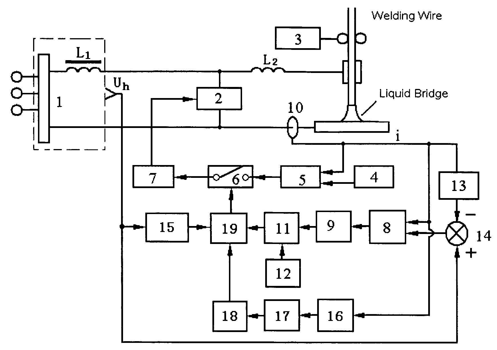
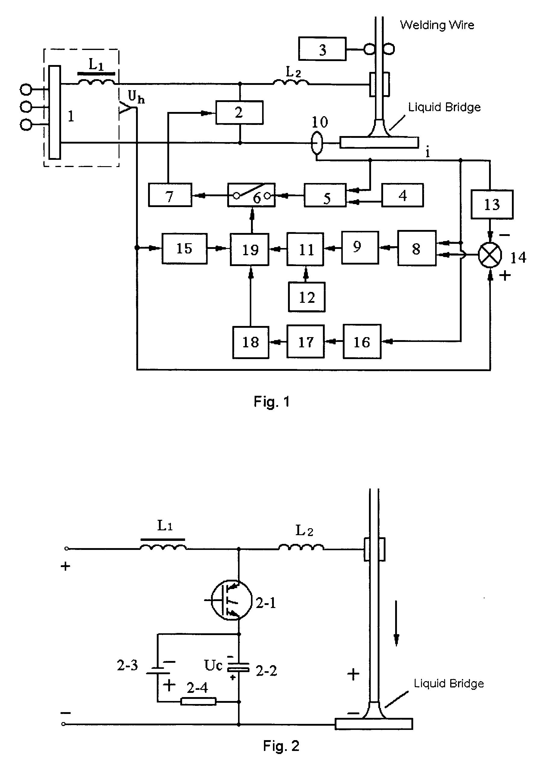
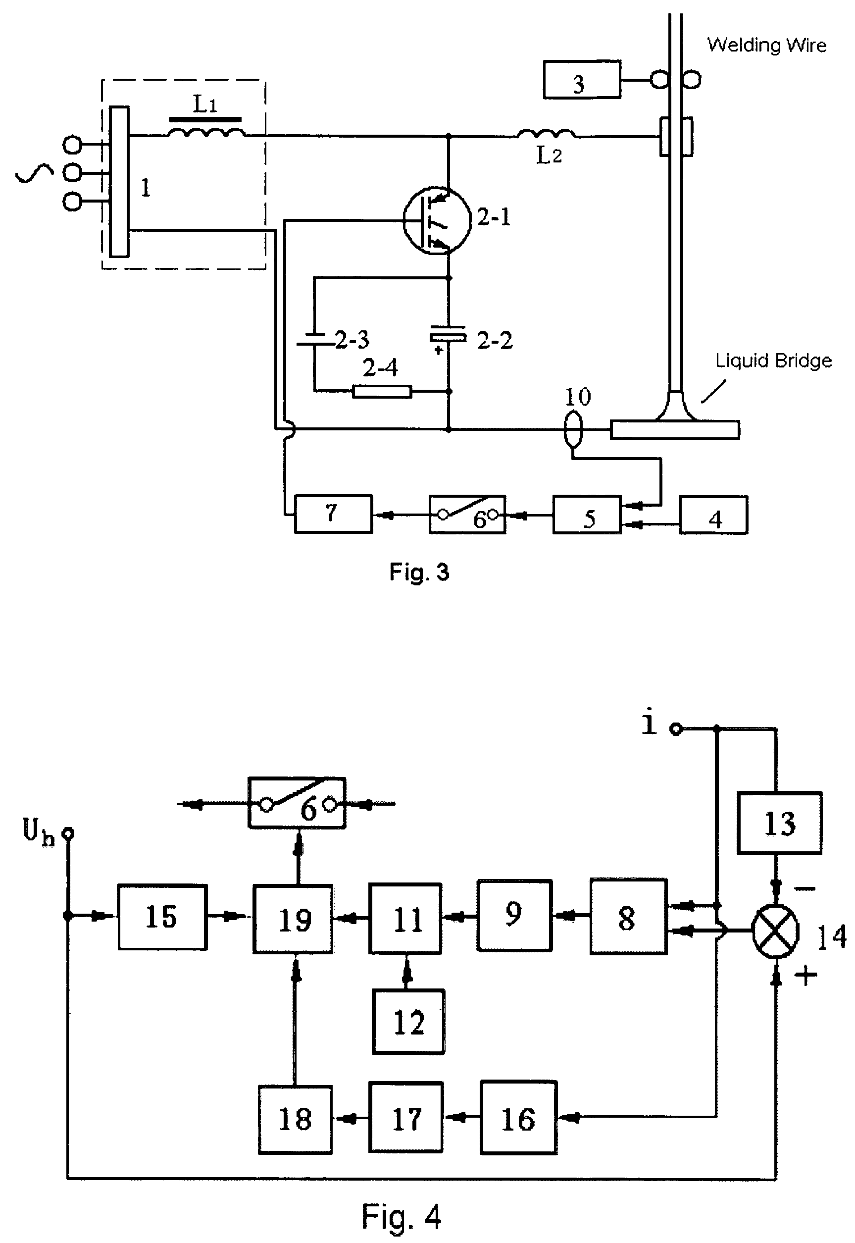
[0111]FIG. 8 shows the basic circuit diagram of the short-circuit liquid bridge state detecting and estimating subsystem. The function of the subsystem is to detect and estimate the short-circuit liquid bridge state during shrinkage process. The resistance changing rate of the welding circuit loop or the impedance changing rate of the welding circuit loop is introduced to represent the diameter or the state of the short-circuit liquid bridge during the bridge shrinkage process, and they are compared with a preset value. If The resistance changing rate or the impedance changing rate of the welding circuit loop reaches the critical preset value, a trigger will be sent out to turn on the closed loop feedback bypass control subsystem for the short-circuit liquid bridge current.

[0112]The circuit works in the way as described below.

[0113]The voltage u is measured at the output of the welding power source, and the liquid bridge current i is detected by the current sensor in the welding cir...


PUM

PropertyMeasurementUnit
currentaaaaaaaaaa
voltageaaaaaaaaaa
resistanceaaaaaaaaaa

Abstract

A method for reducing spatter in the short-circuit transfer gas shielded arc welding is disclosed. In this method, the resistance changing rate or the impedance changing rate of the welding circuit loop is detected for estimating the diameter of the short-circuit liquid bridge. When the diameter of the short-circuit liquid bridge shrinks to the preset value, the short-circuit bridge current is bypassed or shunted by the current closed loop feedback bypass control, and the current is decreased to a very low level rapidly and maintained this level until the bridge is broken, which results in a gentle and smooth drop transfer in a low current level condition, so as to avoid the mass spatter. Furthermore, a system for performing the method has also been disclosed.

Description

FIELD OF THE INVENTION[0001]The invention relates to the field of the welding process and welding equipment, especially to a method for reducing spatter in short-circuit transfer gas shielded arc welding and a system for performing the method.BACKGROUND OF THE INVENTION[0002]Short-circuit transfer gas shielded arc welding, which is a gas shielded consumable electrode arc welding process, includes carbon dioxide gas shield arc welding, mixed gas shield arc welding and argon shielded consumable electrode arc welding, in which a melting drop is deposited from a welding wire or electrode onto a workpiece in a short-circuit transfer mode. Because of it's high productivity, low cost, small welding distortion, popular adaptability, easy to be employed in all-position welding and easy to be automatized, short-circuit transfer gas shield arc welding has wide impact in industry applications. The major disadvantage of short-circuit transfer gas shield arc welding is the huge amount of the weld...

Claims


Application Information

Patent Timeline
Patent Type & Authority Patents(United States)
IPC IPC(8): B23K9/095B23K9/073B23K9/10
CPCB23K9/073B23K9/1043
Inventor OU, ZHIMING
Owner TSINGHUA UNIV
Learn More