
Shunt type voltage regulator

a voltage regulator and shunt technology, applied in the direction of electric variable regulation, process and machine control, instruments, etc., can solve the problems of insufficient response at higher frequencies (greater than 1 mhz), considerable power consumption at the high limit of an external power supply range, and less suitable arrangement for other applications. , to achieve the effect of low current and lower speed regulation respons

Inactive Publication Date: 2007-08-28
MONTEREY RES LLC
View PDF34 Cites 19 Cited by
  • Summary
  • Abstract
  • Description
  • Claims
  • Application Information

AI Technical Summary

Benefits of technology

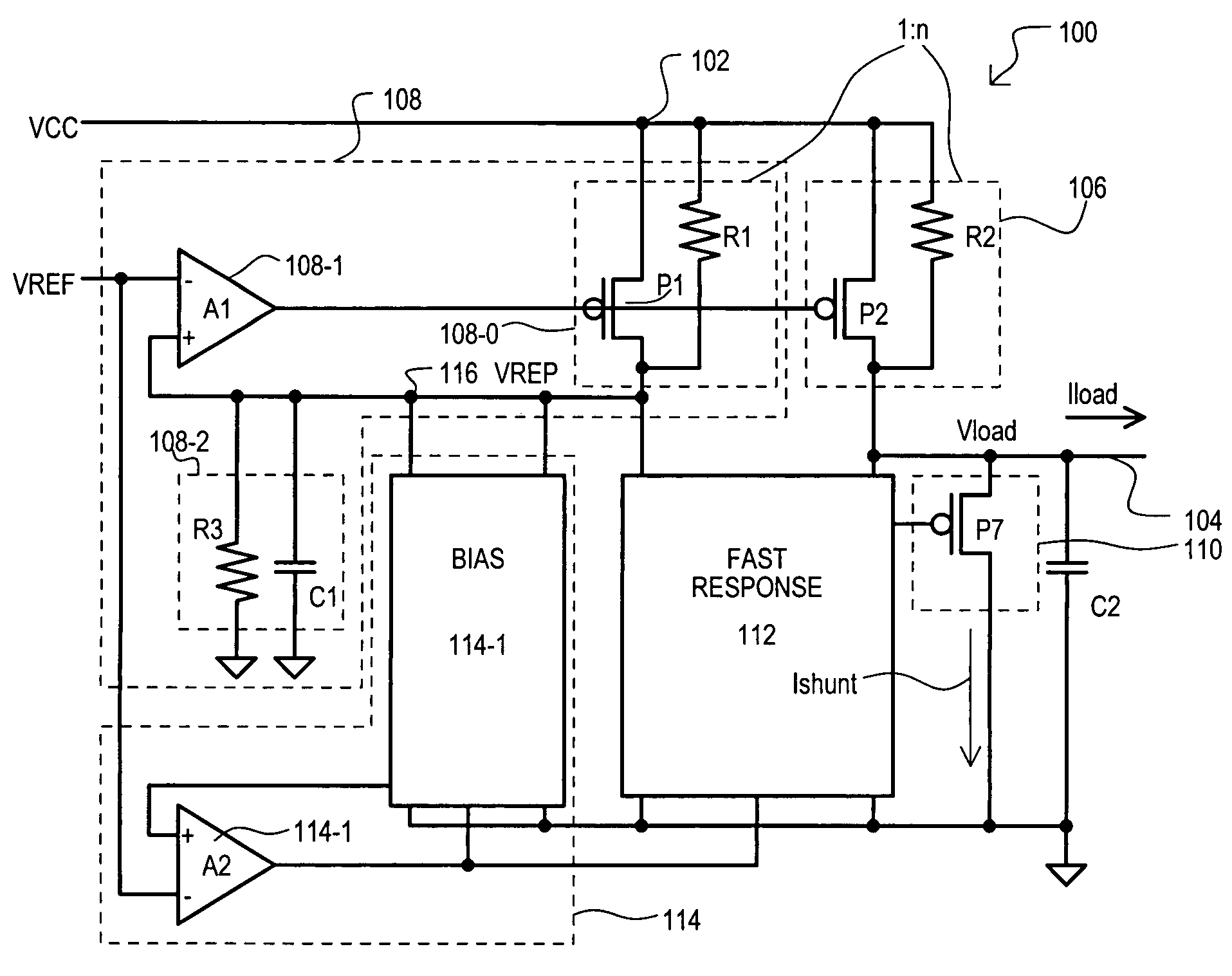
[0009]A voltage regulator circuit can include a first feedback circuit with a modulated feedback impedance. Such a first feedback circuit can include a first amplifier with a first input coupled to a reference node, a second input coupled to a load replication node, and an output. In addition, a modulated impedance feedback circuit can be coupled between the load replication node and a power supply node. The modulated impedance feedback circuit can include a feedback resistor and transistor connected in parallel between the power supply node and the load replication node. A control terminal of the feedback transistor can be coupled to the output of the first amplifier. Such an arrangement can generate a potential at the load replication node without having to draw large amounts of current at the upper limits of a power supply voltage.
[0012]In such an arrangement, the impedance path providing current to a load node can be modulated in the same fashion as the feedback impedance. Thus, a load supply transistor can operate in the linear range, and thus provide power savings at higher power supply limits as large amounts of current need not be shunted from the load, as can occur in the above conventional case.
[0013]According to another aspect of the embodiments, a voltage regulator circuit can further include a replication response circuit coupled to the replication node. A replication response circuit can include a reference resistor in parallel with a response capacitor. A response circuit can serve to prevent voltage at a replication node from varying at rates beyond a predetermined bandwidth limit of the first feedback circuit. In this way, a first feedback circuit can provide regulation over a certain frequency range, while a response circuit can provide regulation over another frequency range.
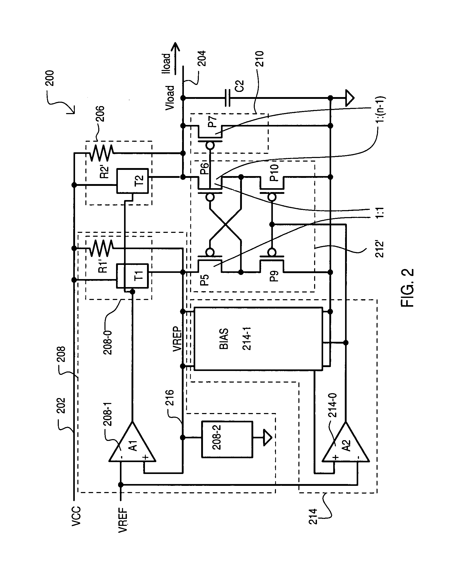
[0014]According to another aspect of the embodiments, a voltage regulator circuit can further include a shunt transistor having source-drain path coupled to a load node and a current conveyor circuit. A current conveyor circuit can include a first conveyor transistor having a source-drain path coupled to the replication node, and a second conveyor transistor having a source-drain path coupled to the load node. Such conveyor transistors can be cross-coupled with respect to one another. In addition, a drain of the first conveyor transistor can be coupled to a gate of the shunt transistor. A width / length (W / L) ratio between the first and second conveyor transistors can be about 1:1, a (W / L) ratio between the second conveyor transistor and the shunt transistor can be about 1:(n−1), where n>2. In such an arrangement, a current conveyor circuit can provide high frequency response to regulating a load node by operation of a current conveyor circuit, which can force the load node to match the replication node.
[0017]The present invention can also include a method of shunt regulating a voltage. The method can include modulating a load supply impedance between a power supply node and a regulated load node with a load supply transistor in the linear region, according to a potential at a replication node. The method can also include modulating a feedback impedance between the power supply node and the replication node with a feedback transistor in the linear region of operation, also according to the potential at the replication node. Such an arrangement can provide low current, lower speed regulation response. The method further includes mirroring the voltage levels between the regulated load node and the replication node, which can provide a high-speed regulation response.
[0018]According to another aspect of the embodiments, the method can include comparing a voltage at the replication node and the reference voltage with feedback path having a unity-gain limit frequency. In addition, the method can include suppressing variations in the voltage at the replication node outside of a unity-gain frequency of the feedback path with at least one response circuit.

Problems solved by technology

While arrangements like that of Smith can provide appropriate current shunting for certain applications, such arrangements can be less suitable for other applications.
In approaches like Smith, there can be considerable power consumption at the high limit of an external power supply range, as each time the power supply voltage exceeds the regulation limit, by even a relatively small amount, the amplifier can drive the shunting device (e.g., transistor) into saturation, and large amounts of current can be shunted to ground.
In addition, such periodic current draws can tax power supply current sourcing capabilities, which may already be strained in high current applications, such as CAM devices, as but one example.
In addition, approaches like that of Smith may provide insufficient response at higher frequencies (greater than 1 MHz).

Method used


Image

  • Shunt type voltage regulator
  • Shunt type voltage regulator
  • Shunt type voltage regulator

Examples


Embodiment Construction

[0023]Various embodiments of the present invention will now be described in detail with reference to a number of drawings. The embodiments describe a shunt-type voltage regulator that can provide shunt type regulation without consuming large amounts of current at the higher end of a power supply range. In addition, such a voltage regulator can provide a regulating response for a wide frequency range with respect to conventional approaches like those described above.

[0024]A shunt-type voltage regulator according to a first embodiment is set forth in FIG. 1 and designated by the general reference character 100. A voltage regulator 100 can receive a power supply voltage (VCC) at a first supply node 102 and provide a regulated voltage (Vload) at a regulated node 104. A load capacitance is represented in FIG. 1 by capacitor C2.

[0025]In the example of FIG. 1, a voltage regulator 100 can include a load supply circuit 106, a first feedback circuit 108, a shunt circuit 110, a fast response c...


PUM


Abstract

A shunt type voltage regulator circuit (300) can include a load supply circuit (306) and feedback circuit (308-0) that provide impedance modulated according to a first feedback circuit (308), thus limiting power consumption at higher power supply ranges. In addition, a faster regulation response can be provided by a current conveyor circuit (312′) that can force the voltage at a regulated load node (304) to match that at a replication node (316).

Description

TECHNICAL FIELD[0001]The present invention relates generally to voltage regulator circuits, and more particularly to shunt type voltage regulator circuits.BACKGROUND OF THE INVENTION[0002]Voltage regulator circuits can serve numerous purposes in integrated circuit devices. One particular application can be to regulate an internal power supply voltage for certain sections of an integrated circuit device. Even more particularly, voltage regulators can supply a power supply voltage to memory cell arrays within memory devices, such as content addressable memories (CAMs), static random access memories (SRAMs) and dynamic RAMs (DRAMs), as but a few of the many possible applications.[0003]Among the various types of voltage regulators are “shunt” type regulators. A typical shunt regulator provides a shunting current path from a load (i.e., the regulated node). When a voltage to the load exceeds a predetermined amount, the shunt path can be enabled, and typically, a large amount of current i...

Claims


Application Information

Patent Timeline
IPC IPC(8): G05F1/40G05F3/16
CPCG05F1/56
Inventor GRADINARIU, IULIAN
Owner MONTEREY RES LLC
Learn More