
Single end planar magnetic speaker

a single-end, magnetic speaker technology, applied in the direction of transducer details, electrical transducers, fibre diaphragms, etc., can solve the problems of unreachable market acceptance, past 65 years of evolution, controlling competitive issues, etc., to achieve equal performance, small size, and favorable construction cost

Inactive Publication Date: 2007-07-31
LRAD CORPORATION
View PDF40 Cites 17 Cited by
  • Summary
  • Abstract
  • Description
  • Claims
  • Application Information

AI Technical Summary

Benefits of technology

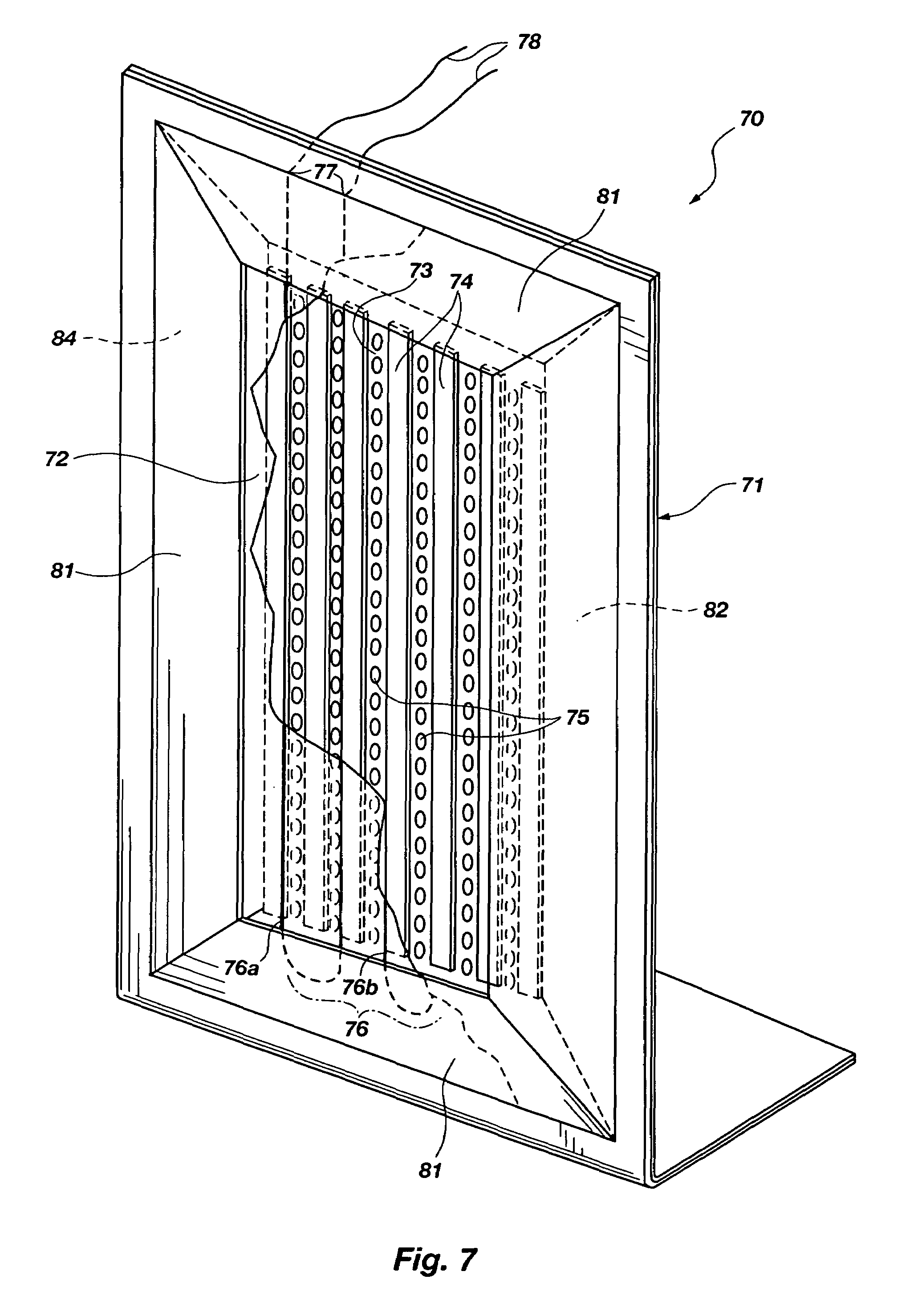
[0019]In another more detailed aspect, the width of a magnetic structure can be made greater than the thickness of a magnetic structure. The mounting structure can include a loading barrier adjacent to and at a predetermined distance in front of a portion of the front side of said diaphragm. This barrier can be adjacent a portion of both the front and back sides of said diaphragm. Furthermore, the system can include at least one proximity loading baffle positioned at a periphery of the diaphragm and substantially enclosing a partially confined volume of air between the diaphragm and loading barrier to maintain substantially balanced loading of the diaphragm during audio reproduction.
[0030]In another more detailed aspect, a method for shrinking a vibratable film for use with a bonded electrically conductive circuit disposed thereon, can include the steps of: a) selecting a film of polyethylenenaphthalate having thickness of less than 100 microns and having the conductive circuit disposed on a side of the film; b) applying ultraviolet radiation at the side of the film having the conductive circuit; and, c) maintaining the ultra violet radiation for sufficient time to shrink dimensions of a portion of the film which is not bonded to the conductive circuit, without causing significant shrinkage of the film which is bonded to the conductive circuit, thereby preserving an integral and unwrinkled attachment configuration between the film and circuit.

Problems solved by technology

It represents a bridging technology between the dynamic and electrostatic speaker designs; however, it has not achieved any significant level of market acceptance over the past 65 years of evolution.
As with any speaker, competitive issues are controlling.
This structure necessitates the use of complex and mechanically challenging design requirements to keep the opposing magnets properly positioned.
This constant force can easily disrupt long term performance of the speaker by causing gradual shifting of mechanical structure within the speaker.
This, again, increases manufacturing costs necessary to counteract this destructive displacement.
Additional problems which require attention involve tunneling of sound and diffusion of certain bandwidths.
This also causes high frequency problems of peaks and premature attenuation.
Other problems are well known in the industry, and include issues set forth in the following patents which are incorporated by reference.
Because of this, single end devices have not been acceptable for commercial applications.
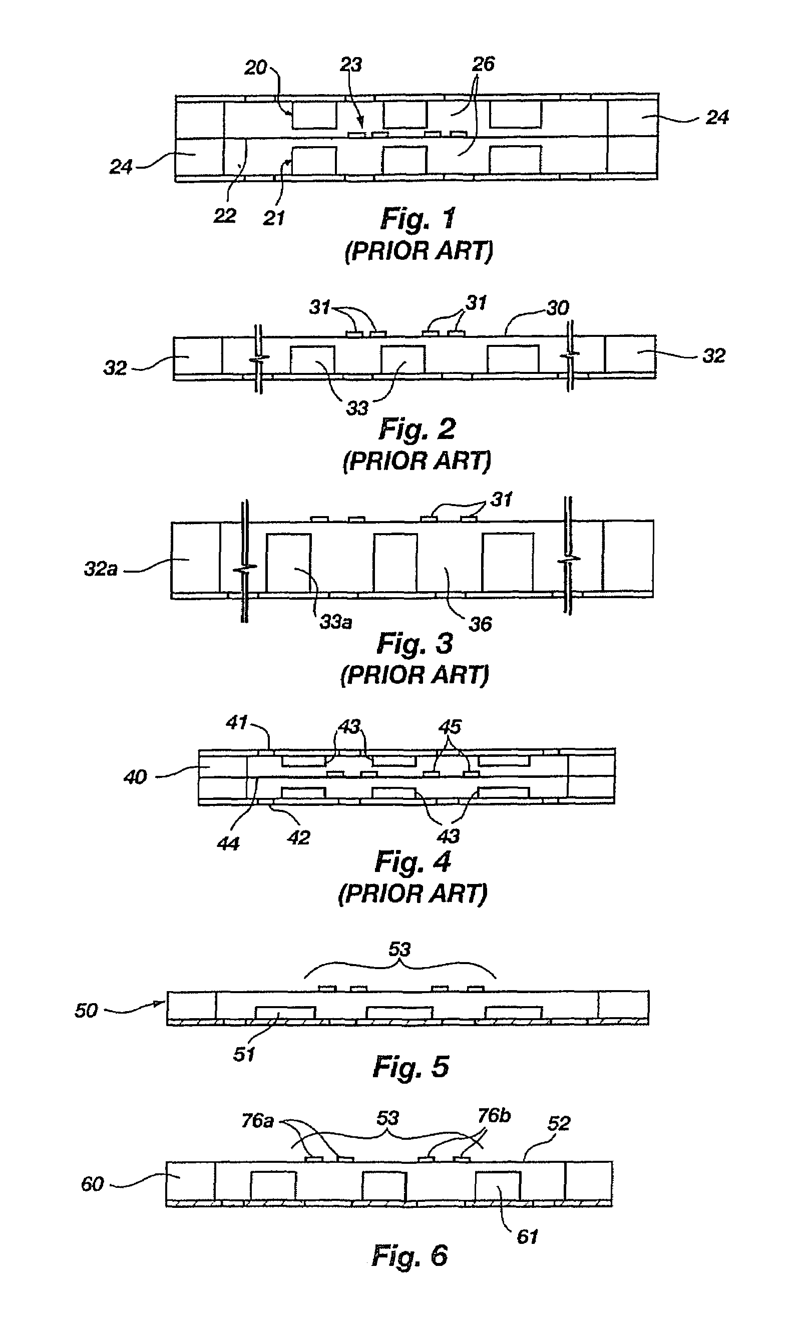
In fact, the increased magnet size results in deeper channels or tunnels 36, further complicating the design of the speaker.
As a result of the perception that increasing magnet thickness is not a practical approach for enhancing power, single end devices are generally characterized by large size and comparatively low efficiency.
Theoretically, the low efficiency of this single end system requires large surface area in order to achieve the necessary displacement of air volume.
This large size imposes significant strain on production requirements and long term performance.
The difficulties of manufacturing by cost effective methods is particularly troublesome with large planar magnetic structures, as it is with large electrostatic speakers.
Failure to maintain uniform alignment of the diaphragm with respect to the driving magnetic field is a major problem.
Therefore, slight deviations from proper positioning can result in serious aberrations in acoustic output.
Maintaining correct spacing for each magnet and the associated section of moveable diaphragm over large surface areas is difficult to efficiently manufacture and subsequently maintain over years of expected performance.
These unique manufacturing requirements result in higher costs for such large structures, particularly in view of the stabilizing structure that must be added to rigidly secure speaker components at desired positions, despite movement and speaker impact that is foreseeable during normal use.
These conditions have resulted in high cost, which has severely limited the marketability of the single end speaker.
In addition to adverse cost impact, the large size requirement of single end systems has significantly limited practical use.
Most speaker applications require smaller sizes because of the limited space available.
In addition to the large volume of space required, single end planar magnetic speakers are generally heavy and cumbersome.
Here again, this requirement for large size is in direct opposition market trends of compactness and low profile.
This lack of successful development over a period of more than fifty years provides strong evidence of obstacles within this technology requiring creative invention.
Even the appearance over the last decade of high energy magnets such as those of neodymium has failed to lead to improvements, particularly within the single end speaker structure.
These forces are magnitudes higher than prior art ceramic magnet structures, further increasing the cost and complexity of a viable speaker device.

Method used


Image

  • Single end planar magnetic speaker
  • Single end planar magnetic speaker
  • Single end planar magnetic speaker

Examples


Embodiment Construction

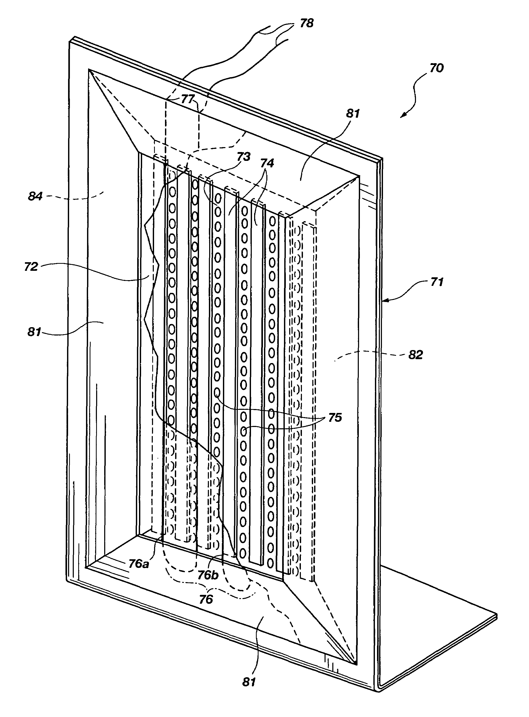
[0051]FIGS. 5 and 6 illustrate one of the basic discoveries of the present invention which has enable the accomplishment of an inexpensive planar magnetic speaker device which is small in size and surprisingly high in quality audio performance. It includes a surprising observation that, unlike prior art ceramic magnets, a high energy magnet such as neodymium as applied in a double ended or push pull tweeter system, can be doubled in thickness and will generate an additional 3 to 6 dB in acoustic output. This is in direct contrast with prior art experience with ceramic or ferrite magnets of common flux density in planar magnetic systems. In other words, it has been discovered that high energy magnets have the unexpected property of generating greater SPL with increased thickness dimensions than prior art ceramic or ferrite based magnets. Specifically, when the magnetic structure is designed as set forth hereafter, it is sufficiently thin to yield at least a 3 dB increase in SPL based...


PUM


Abstract

A single end planar magnetic speaker system having at least one thin film, flexible diaphragm (72, 90) having a front side and a rear side for converting an input electrical signal into a corresponding acoustic output, the at least one diaphragm including a predetermined conductive region (76) and a predetermined non-conductive region; a magnetic structure (92) utilizing nonferite high energy magnets of a predetermined thickness wherein the magnets are each at least as wide as they are deep; the magnets having a magnetic strength wherein when compared to magnets of a ferrite type of same width as the nonferite high energy magnets but which have increased depth to yield at least nearly the same magnetic strength as the high energy magnets in the magnetic structure, doubling the depth of the high energy magnets in the magnetic structure, doubling the depth of the high energy magnets in the magnetic structure yields an increase in speaker sensitivity of at least 3 dB while the doubling the depth of the ferrite type magnet will yield a gain of less than 3 dB, and the system further includes a mounting structure coupled to the diaphragm to capture the diaphragm, to hold it in a predetermined state of tension and space it at a predetermined distance from the magnetic structure.

Description

FIELD OF THE INVENTION[0001]This invention relates to planar magnetic speakers, and in particular to single end planar magnetic speakers capable of audio output least within the mid and upper audio frequency ranges, and preferably within the full audio range.PRIOR ART[0002]Two general types of loudspeakers comprise (i) dynamic and (ii) electrostatic. A third loudspeaker type representing a more limited area of acoustic reproduction is the planar magnetic speaker. It represents a bridging technology between the dynamic and electrostatic speaker designs; however, it has not achieved any significant level of market acceptance over the past 65 years of evolution. Indeed, planar magnetic speakers comprise much less than one percent of an audio speaker industry. It is clearly a field of acoustic technology which has remained exploratory.[0003]As with any speaker, competitive issues are controlling. In addition to quality, a truly competitive speaker must be reasonable in price, practical ...

Claims


Application Information

Patent Timeline
IPC IPC(8): H04R7/04H04R9/06H04R9/04
CPCH04R9/047H04R7/04H04R7/18H04R7/24H04R9/025H04R31/003H04R2307/029
Inventor GRAEBENER, DAVID
Owner LRAD CORPORATION
Learn More