
CMOS image sensor and method for fabricating the same

a technology of image sensor and manufacturing method, which is applied in the field of cmos image sensor, can solve the problems of high power consumption, complicated driving method, and charge coupled device (ccd), and achieve the effect of reducing the darkcurrent and reducing the darkcurrent of the cmos image sensor

Active Publication Date: 2007-06-19
III HLDG 4
View PDF7 Cites 40 Cited by
  • Summary
  • Abstract
  • Description
  • Claims
  • Application Information

AI Technical Summary

Benefits of technology

The solution effectively decreases darkcurrent by preventing ion implantation defects and recombining electron-hole pairs in the P+ type diffusion area, thereby improving device efficiency and charge transfer efficiency.

Problems solved by technology

However, the charge coupled device (CCD) has disadvantages of a complicated driving method, high power consumption, and a complicated fabrication process requiring a multi-phased photo process.
In the charge coupled device (CCD), a control circuit, a signal processing circuit, an analog to digital (A / D) converter circuit, and so on cannot be easily integrated into a charge coupled device chip, thereby having the problem of forming compact-size products.
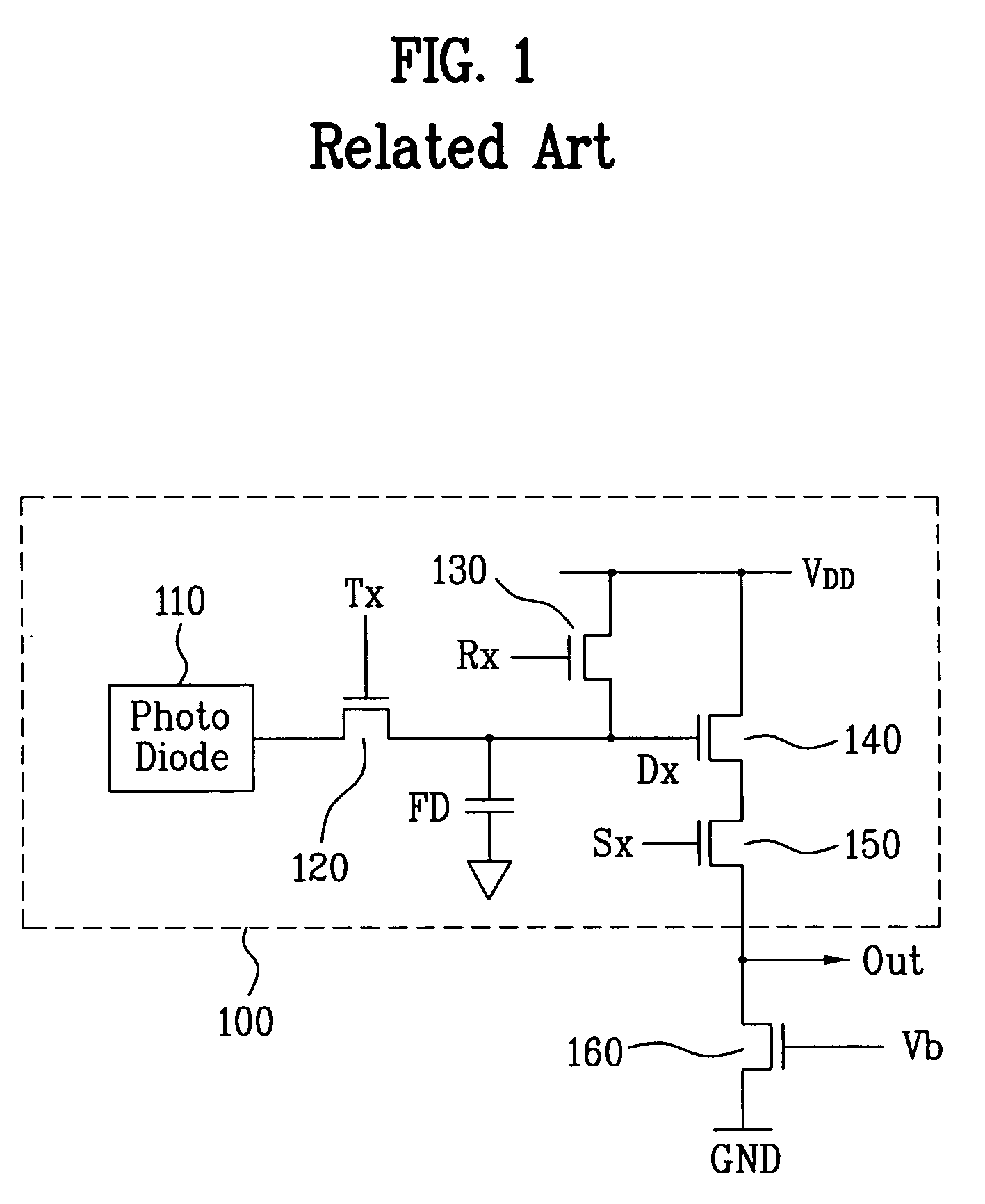
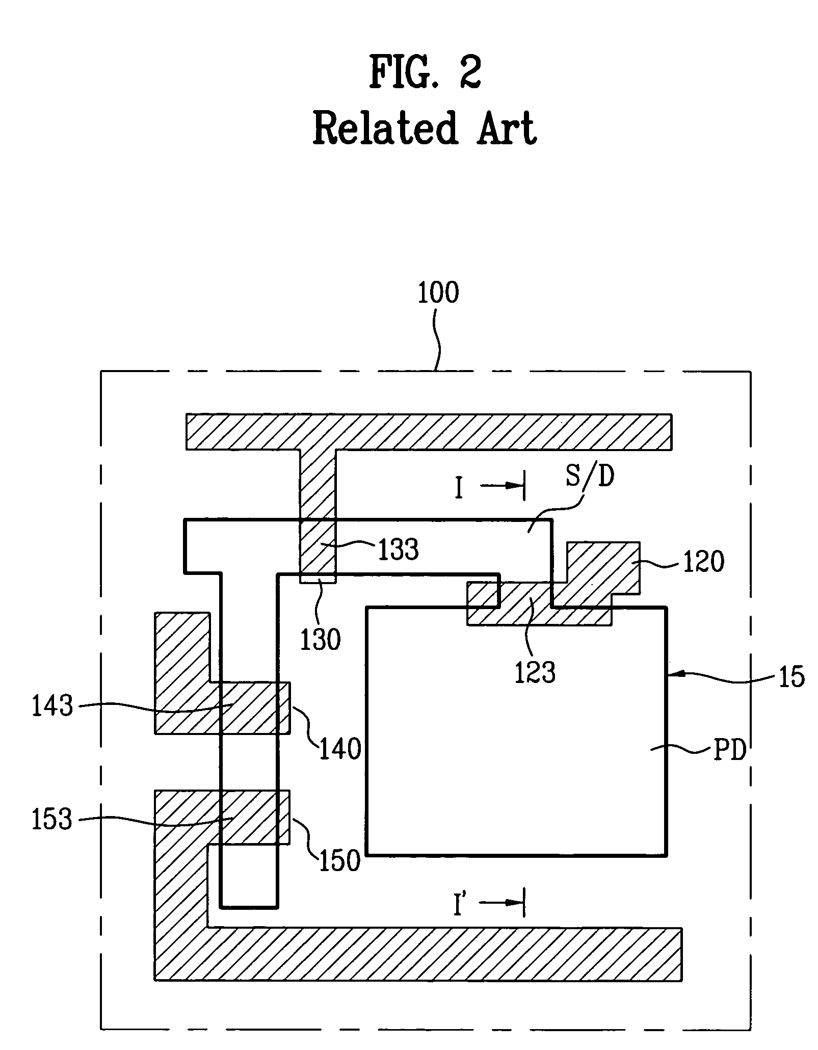
However, the related art CMOS image sensor having the aforementioned structure has the problems of low device efficiency and low charge storing capacity due to the increase of a darkcurrent.
Under the circumstance of low illumination, the darkcurrent may generate the serious problems such as low device efficiency and low charge storing capacity in the CMOS image sensor.
Accordingly, the related art CMOS image sensor may have the damage due to the impurity implantation in the boundary between the n− type diffusion area and the P° type diffusion area and the device isolation layer, and furthermore, may have the defect.
As a result, a leakage current of the photodiode PD increases, whereby the darkcurrent of the CMOS image sensor increases.
As a result, it is difficult to prevent the increase of the darkcurrent generated in the boundary between the device isolation layer and the active area for the photodiode PD, so that it has the limitation to the decrease of the darkcurrent.

Method used


Image

  • CMOS image sensor and method for fabricating the same
  • CMOS image sensor and method for fabricating the same
  • CMOS image sensor and method for fabricating the same

Examples


first embodiment

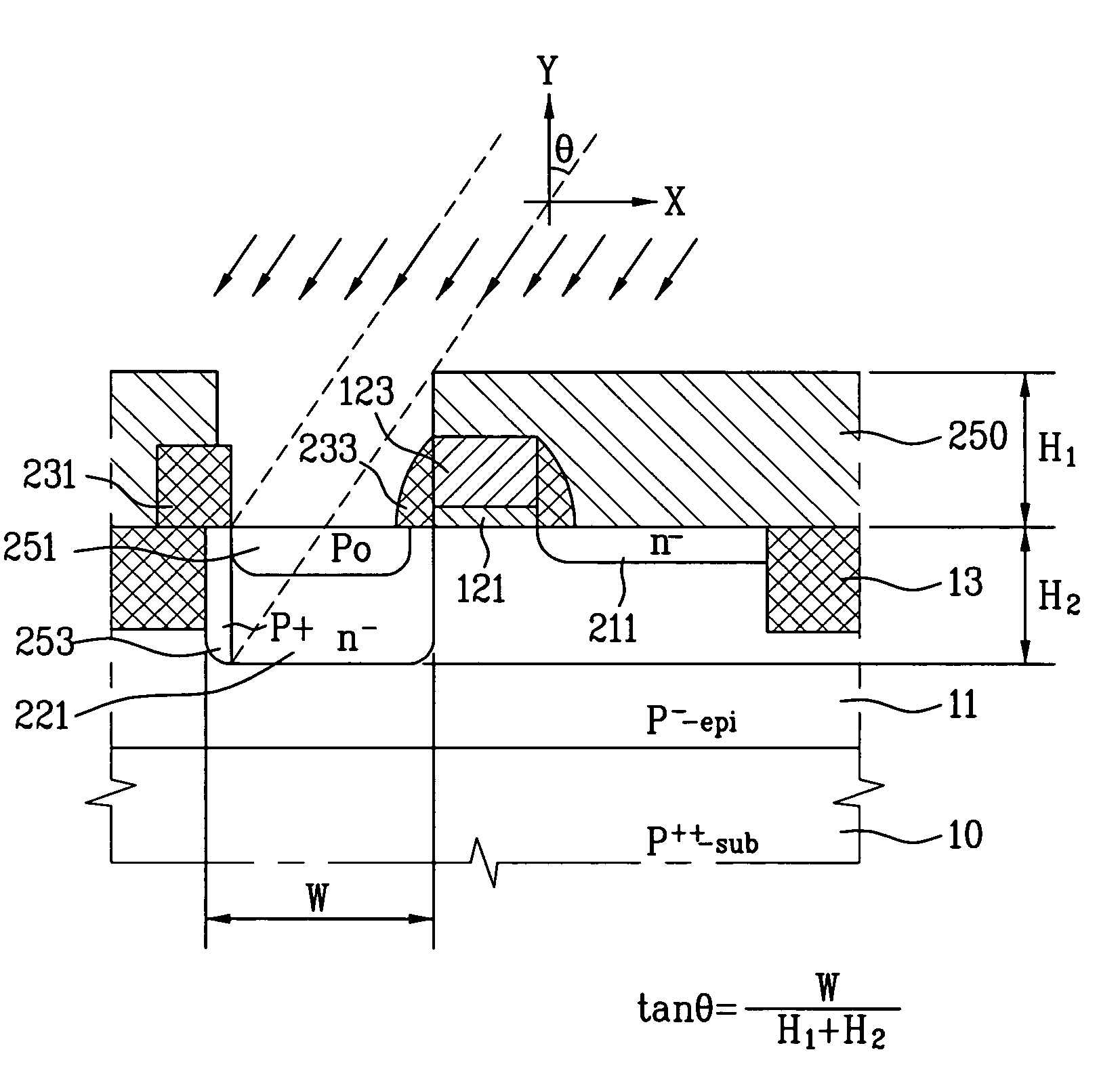
[0070]FIG. 5 is a cross sectional view of the photodiode along II–II′ of FIG. 4 according to the present invention.

[0071]In the CMOS image sensor according to the first embodiment of the present invention, as shown in FIG. 5, a P− type epitaxial layer 11 is formed on a P++ type semiconductor substrate 10. The semiconductor substrate 10 may be formed of a crystal silicon substrate. To define and active area, a device isolation layer 13 is formed in a device isolation area of the semiconductor substrate 10. The device isolation layer 13 is formed in an STI (shallow trench isolation) process or an LOCOS (local oxidation of silicon) process. In this structure, a gate insulating layer 121 and a gate 123 are formed on the active area of the epitaxial layer 11 for the transfer transistor 140 of FIG. 4. Then, insulating layers 233 are formed at both sidewalls of the gate 123.

[0072]After that, an n− type diffusion area 221 and a P° type diffusion area 251 are formed in the epitaxial layer 11...

second embodiment

[0089]In the CMOS image sensor according to the present invention, as shown in FIG. 7, a P− type epitaxial layer 11 is formed on a P++ type semiconductor substrate 10. The semiconductor substrate 10 may be formed of a crystal silicon substrate. To define an active area, a device isolation layer 13 is formed in a device isolation area of the semiconductor substrate 10. The device isolation layer 13 may be formed in an STI (shallow trench isolation) process or an LOCOS (local oxidation of silicon) process. In this structure, a gate insulating layer 121 and a gate 123 are formed in the active area of the epitaxial layer 11 for the respective transistors explained in FIG. 4. Then, sidewall insulating layers 233 are formed at both sidewalls of the gate 123.

[0090]After that, an n− type diffusion area 221 and a P° type diffusion area 251 are formed in the epitaxial layer 11 of a photodiode PD. The P° type diffusion area 251 is formed on the n− type diffusion area 221. Also, source / drain re...

third embodiment

[0104]In the CMOS image sensor according to the present invention, as shown in FIG. 9, a P− type epitaxial layer 11 is formed on a P++ type semiconductor substrate 10. The semiconductor substrate 10 may be formed of a crystal silicon substrate. To define an active area, a device isolation layer 406a is formed in a device isolation area of the semiconductor substrate 10. The device isolation layer 406a is formed to have a higher surface than that of the epitaxial layer 11. In this structure, a gate insulating layer 121 and a gate 123 are formed in the active area of the epitaxial layer 11 for the transfer transistor 120, the reset transistor 130, the drive transistor 140, and the select transistor 150 explained in FIG. 4. Also, sidewall insulating layers 233 are formed at both sidewalls of the gate 123.

[0105]After that, an n− type diffusion area 221 and a P° type diffusion area 251 are formed in the epitaxial layer 11 of a photodiode PD. The P° type diffusion area 251 is formed on th...


PUM


Abstract

A CMOS image sensor and a method for fabricating the same is disclosed, to decrease a darkcurrent generated in the boundary between a diffusion area of a photodiode and a device isolation layer, which includes a first conductive type semiconductor substrate having an active area and a device isolation area, the active area including a photodiode and a transistor; a device isolation layer formed in the device isolation area of the semiconductor substrate; a second conductive type diffusion area formed in the photodiode of the semiconductor substrate at a predetermined interval from the device isolation layer; a gate insulating layer and a gate electrode formed in the transistor of the semiconductor substrate; and a first conductive type first diffusion area formed in the semiconductor substrate of the boundary between the second conductive type diffusion area and the device isolation layer.

Description

[0001]This application claims the benefit of the Korean Application Nos. P2003-75424 filed on Oct. 28, 2003, P2003-75417 filed on Oct. 28, 2003, and P2003-101547 filed on Dec. 31, 2003, which are hereby incorporated by reference.BACKGROUND OF THE INVENTION[0002]1. Field of the Invention[0003]The present invention relates to a CMOS image sensor, and more particularly, to a CMOS image sensor and a method for fabricating the same, to decrease a darkcurrent generated in the boundary between a diffusion area of a photodiode and a device isolation layer.[0004]2. Discussion of the Related Art[0005]Generally, an image sensor is a semiconductor device for converting an optical image into an electric signal. The image sensor can be broadly categorized into a charge coupled device (CCD) and a complementary metal oxide semiconductor (CMOS) image sensor.[0006]The charge coupled device (CCD) includes a plurality of photodiodes (PD) aligned in a matrix-type configuration and converting light signa...

Claims


Application Information

Patent Timeline
Patent Type & Authority Patents(United States)
IPC IPC(8): H01L21/339H01L27/146H04N25/00
CPCH01L27/1463H01L27/14643H01L27/14687H01L27/14689
Inventor HAN, CHANG HUN
Owner III HLDG 4
Learn More