
Magnetic recording medium, method for producing the same, and magnetic recording apparatus

a recording medium and magnetic technology, applied in the field of magnetic recording medium, a method for producing the same, and a magnetic recording apparatus, can solve the problems of fine and minute crystal grains, and deterioration of magnetic characteristics of the recording layer, so as to achieve high density recording, high magnetostatic characteristics, and low noise in the medium

Inactive Publication Date: 2007-06-05
HITACHT MAXELL LTD
View PDF8 Cites 35 Cited by
  • Summary
  • Abstract
  • Description
  • Claims
  • Application Information

AI Technical Summary

Benefits of technology

[0016]Accordingly, in the oxide-containing CoPtCr-based alloy medium based on the perpendicular magnetic recording system of the present invention, the recording layer is composed of a plurality of magnetic layers having different oxide concentrations. The crystal grains are large and the magnetic characteristics are improved in the magnetic layer having the lower oxide concentration. On the other hand, the magnetic characteristics are deteriorated in the magnetic layer having the higher oxide concentration, but the crystal grains are fine and minute. When the recording layer is formed by stacking or laminating the magnetic layer having the low oxide concentration and the magnetic layer having the high oxide concentration as in the magnetic recording medium of the present invention, the deterioration of the magnetic characteristics of the magnetic layer having the high oxide concentration is supplemented by the magnetic characteristics of the magnetic layer having the low oxide concentration. Therefore, the magnetization characteristic of the entire recording layer of the present invention is improved as compared with a case in which the recording layer is formed of only a magnetic layer having a high oxide concentration. As a result, it is possible to suppress the deterioration of the magnetic characteristics by constructing the recording layer with the plurality of magnetic layers having the different oxide concentrations.
[0042]Therefore, for example, it is assumed that the recording layer is formed of the two magnetic layers (first and second recording layers) and the first recording layer is formed on the side of the underlayer. On this assumption, when the first recording layer is formed by means of the RF sputtering method and the second recording layer is formed by means of the DC sputtering method, then the oxide concentration of the first recording layer is higher than the oxide concentration of the second recording layer. Thus, the magnetic recording medium of the present invention as defined in the first aspect is obtained. When the production method as described above is used, it is possible to decrease the number of sputtering targets having different oxide concentrations to be prepared.

Problems solved by technology

However, as described above, if the oxide concentration becomes too high, a problem arises such that the magnetic characteristics of the recording layer are deteriorated.
On the other hand, the magnetic characteristics are deteriorated in the magnetic layer having the higher oxide concentration, but the crystal grains are fine and minute.

Method used


Image

  • Magnetic recording medium, method for producing the same, and magnetic recording apparatus
  • Magnetic recording medium, method for producing the same, and magnetic recording apparatus
  • Magnetic recording medium, method for producing the same, and magnetic recording apparatus

Examples


example 1

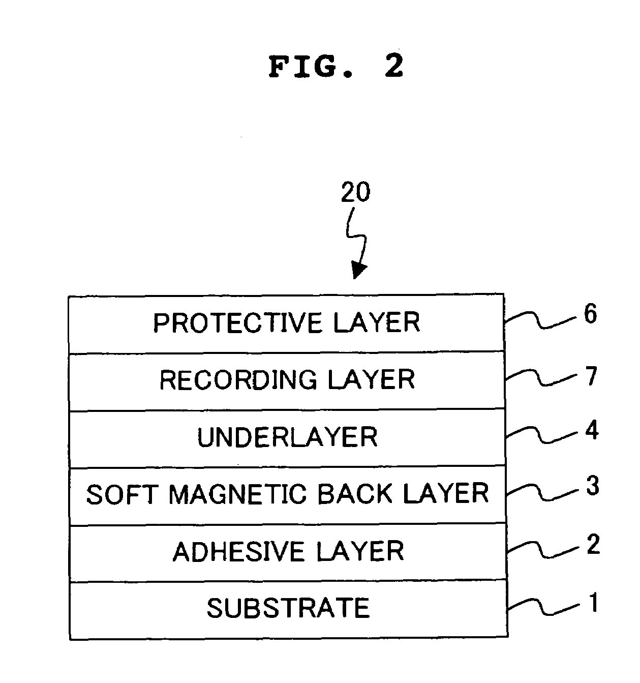
[0054]FIG. 1 shows a schematic sectional view illustrating a magnetic disk manufactured in Example 1. As shown in FIG. 1, the magnetic disk 10 manufactured in Example 1 has such a structure that an adhesive layer 2, a soft magnetic back layer 3, an underlayer 4, a first recording layer 5a, a second recording layer 5b, and a protective layer 6 are successively stacked on a substrate 1. In Example 1, a two-layered structure was formed by the first recording layer 5a and the second recording layer 5b to construct a recording layer 5.

[0055]The adhesive layer 2 is a layer provided to avoid any exfoliation between the substrate 1 and the film stacked or laminated thereon. The soft magnetic back layer 3 is a layer provided to converge the magnetic field applied to the recording layer when information is recorded. The underlayer 4 is a layer provided to improve the crystalline orientation of the first recording layer 5a and the second recording layer 5b. The first recording layer 5a and the...

example 2

[0084]As for a magnetic disk manufactured in Example 2, targets having an identical composition were used when a first recording layer 5a and a second recording layer 5b were formed by means of the sputtering. The first recording layer 5a was formed by means of the RF sputtering method, and the second recording layer 5b was formed by means of the DC sputtering method. The composition of the target was Co70Pt20Cr10 (at. %)-SiO2 (CoPtCr:SiO2=88:12 mol %). As for the sputtering condition for the first recording layer 5a, the gas pressure was 4.2 Pa, the input electric power was 400 W, and the film thickness was 5 nm. On the other hand, as for the sputtering condition for the second recording layer 5b, the gas pressure was 4.2 Pa, the input electric power was 250 W, and the film thickness was 10 nm. The magnetic disk was manufactured in the same manner as in Example 1 except for the above.

[0085]The oxide concentrations of the first recording layer 5a and the second recording layer 5b of...

example 3

[0089]FIG. 7 shows a schematic sectional view illustrating a magnetic disk manufactured in Example 3. As shown in FIG. 7, the magnetic disk 30 manufactured in Example 3 has such a structure that an adhesive layer 2, a soft magnetic back layer 3, an underlayer 4, a first recording layer 5a, a second recording layer 5b, a third recording layer 5c, and a protective layer 6 are successively stacked on a substrate 1. That is, in Example 3, a three-layered structure was formed to construct a recording layer 5. An explanation will be made below about a method for manufacturing the magnetic disk 30 prepared in Example 3.

[0090]At first, a disk-shaped glass substrate having a diameter of 2.5 inches (6.5 cm) was used for the substrate 1. A Ti film was formed as the adhesive layer 2 on the substrate 1 by means of the DC sputtering. As for the sputtering condition, the gas pressure was 0.28 Pa and the input electric power was 500 W. Ti was used for the target. The film thickness of the adhesive ...


PUM

PropertyMeasurementUnit
Thicknessaaaaaaaaaa
Compositionaaaaaaaaaa
Contentaaaaaaaaaa

Abstract

A magnetic recording medium based on the perpendicular magnetic recording system has a substrate which is formed of a non-magnetic material, a soft magnetic back layer which is formed of a soft magnetic material and which is formed on the substrate, an underlayer which is formed on the soft magnetic back layer, and a recording layer which is formed of an alloy magnetic material which is mainly composed of CoPtCr and contains an oxide, and which is formed on the underlayer. The recording layer is formed of two or more magnetic layers having different oxide contents, and the layer, which is included in the two or more magnetic layers for constructing the recording layer and which is provided on a side nearest to the underlayer, has the highest oxide content in the recording layer. The magnetic recording medium has more excellent magnetic characteristics with less medium noise.

Description

BACKGROUND OF THE INVENTION[0001]1. Field of the Invention[0002]The present invention relates to a magnetic recording medium, a method for producing the same, and a magnetic recording apparatus. In particular, the present invention relates to a magnetic recording medium based on the perpendicular magnetic recording system preferably usable for the high density recording, a method for producing the same, and a magnetic recording apparatus.[0003]2. Description of the Related Art[0004]In recent years, the information oriented society is remarkably advanced, and it becomes possible to process, for example, not only the character information but also the voice information and the image information at high speeds. One of the apparatuses capable of processing the information as described above at the high speed is a magnetic recording apparatus which is installed, for example, to the computer. At present, the development is advanced in relation to the magnetic recording apparatus in order ...

Claims


Application Information

Patent Timeline
IPC IPC(8): G11B5/66G11B5/70G11B5/64G11B5/851
CPCG11B5/66G11B5/851G11B5/656G11B5/672
Inventor KODA, TETSUNORIYAMANAKA, HIDEAKIFUJITA, ENJIMATSUNUMA, SATOSHI
Owner HITACHT MAXELL LTD
Learn More