
Humidity sensor and composite sensor having humidity detecting function

a technology of humidity sensor and composite sensor, which is applied in the direction of liquid/fluent solid measurement, fluid pressure measurement, instruments, etc., can solve the problem of no function as this humidity sensor is damaged, and achieve the effect of high precision and detection of humidity

Inactive Publication Date: 2007-05-08
DENSO CORP
View PDF4 Cites 8 Cited by
  • Summary
  • Abstract
  • Description
  • Claims
  • Application Information

AI Technical Summary

Benefits of technology

The solution significantly enhances the sensor's resistance to pollutant attachment and maintains accurate humidity detection by ensuring moisture entry through non-covered areas and allowing for dielectric constant changes to be accounted for in processing, thus improving precision and reliability.

Problems solved by technology

Thus, no function as this humidity sensor is damaged.

Method used


Image

  • Humidity sensor and composite sensor having humidity detecting function
  • Humidity sensor and composite sensor having humidity detecting function
  • Humidity sensor and composite sensor having humidity detecting function

Examples


first embodiment

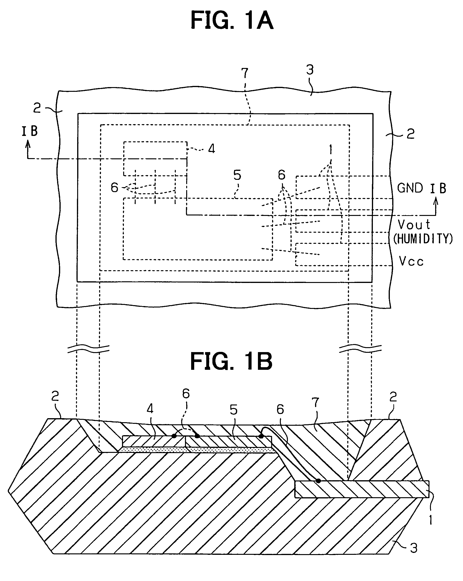
[0044]The first embodiment and modifications thereof will be described with reference to FIG. 1A to FIG. 9.

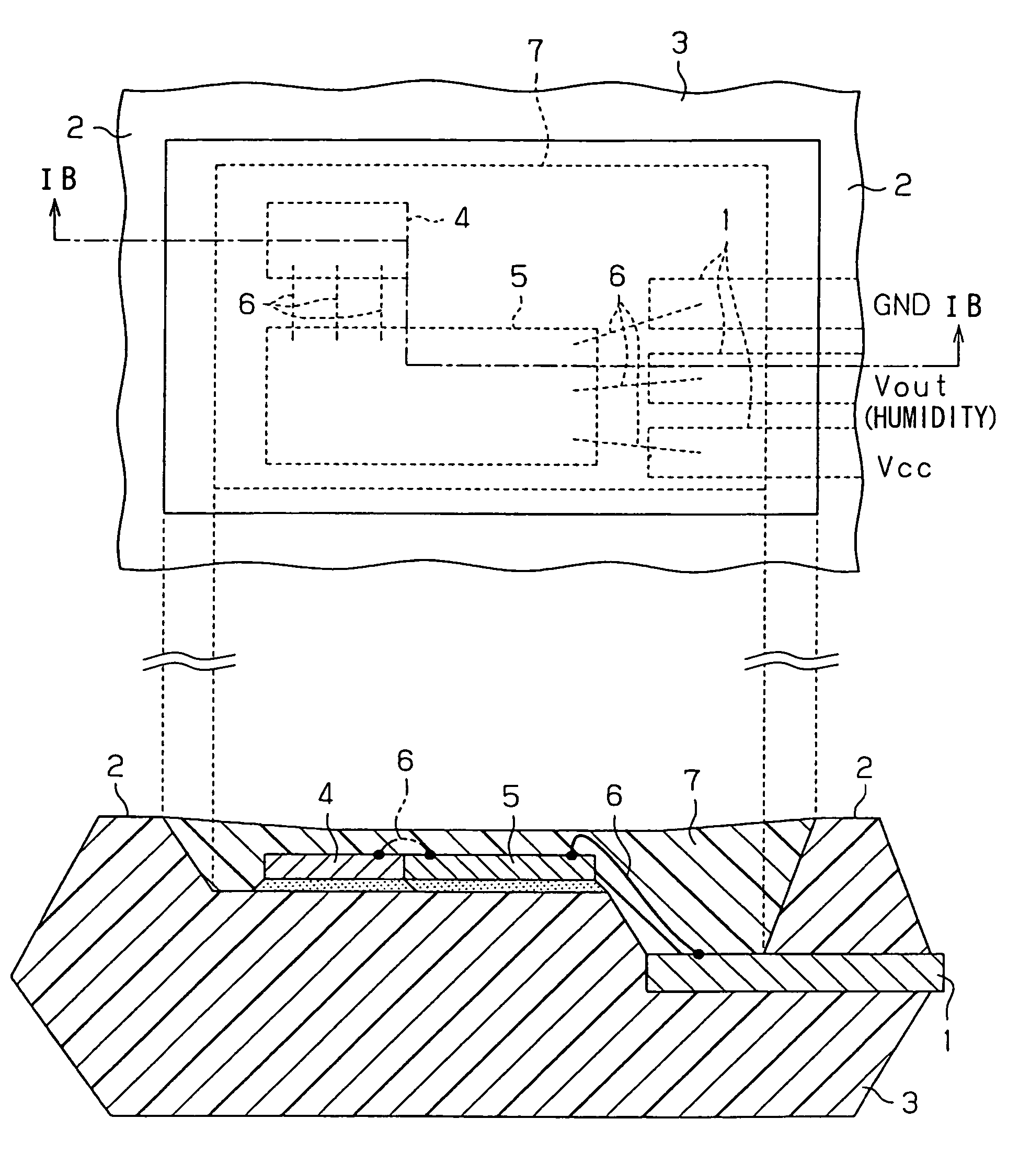
[0045]As shown in FIGS. 1A and 1B, a humidity sensor is insert-molded to a resin molding body 3 having a wall portion 2 as a barrage in the circumference such that conductors 1 (terminal conductor) as sensor terminals are partially guided to the exterior. A humidity sensor chip 4 functioning as the humidity sensor, and a processing circuit chip 5 for electrically processing humidity information obtained from the humidity sensor chip 4 are separately integrated, bonded and fixed to an intermediate portion of this resin molding body 3, i.e., inside the wall portion 2.

[0046]The bonded and fixed humidity sensor chip 4, the processing circuit chip 5 and the conductor 1 as the sensor terminals are electrically connected through bonding wires 6 inside the wall portion 2 of the resin molding body 3. The entire electric connecting portion including the bonding wires 6 is covered with a ...

second embodiment

[0072]As shown in FIGS. 10A and 10B, a composite sensor having a humidity detecting function is insert-molded to a resin molding body 3 having a wall portion 2 as a barrage in the circumference such that conductors 1 (terminal conductors) as sensor terminals are partially guided to the exterior. A humidity sensor chip 4 functioning as a humidity sensor, a well-known pressure sensor chip 8 using e.g., distortion resistance, etc. and functioning as a pressure sensor, and a processing circuit chip 5 for electrically processing humidity and pressure information obtained from both the sensor chips 4, 8 are separately integrated, bonded and fixed to an intermediate portion of this resin molding body 3.

[0073]Further, both the sensor chips 4, 8, the processing circuit chip 5 and the conductors 1, which are adhered and fixed, are electrically connected through bonding wires 6 inside the wall portion 2 of the resin molding body 3. The entire electric connecting portion including this bonding ...


PUM


Abstract

A humidity sensor includes a resin molding body having a wall portion as a barrage, a chip having at least a humidity sensing function and fixed to a portion of the resin molding body inside the wall portion, and a terminal conductor insert-molded in the resin molding body and partially leaded to an exterior of the resin molding body. Here, the terminal conductor is electrically connected to the chip inside the wall portion of the resin molding body. In the humidity sensor, a protecting material having a humidity sensing property is filled in the wall portion and covers an entire electric connecting portion of the chip and the terminal conductor. The structure of the humidity sensor can be suitably used for a composite sensor including a chip having a humidity sensing function.

Description

CROSS REFERENCE TO RELATED APPLICATION[0001]This application is based on Japanese Patent Application No. 2004-240310 filed on Aug. 20, 2004, the contents of which are incorporated herein by reference in its entirety.FIELD OF THE INVENTION[0002]The present invention relates to a humidity sensor and a composite sensor having a humidity detecting function (structure).BACKGROUND OF THE INVENTION[0003]For example, a capacitance-changing type humidity sensor is described in U.S. Pat. No. 6,742,387 (corresponding to JP-A-2003-156464). This humidity sensor is used for detecting humidity within a room to perform humidity control of an air conditioner, or is used for detecting humidity of the outdoors to make a weather observation.[0004]When it is simply called humidity, there is generally relative humidity and absolute humidity. In the relative humidity, the ratio of an amount of water vapor actually included within the atmosphere, to a maximum amount of water vapor (saturated water vapor pr...

Claims


Application Information

Patent Timeline
Patent Type & Authority Patents(United States)
IPC IPC(8): G01F7/00
CPCG01N27/223H01L2224/73265H01L2224/48137H01L2924/181H01L2924/00012
Inventor WATANABE, YOSHIFUMI
Owner DENSO CORP
Learn More