Flexible transponder label which is readable on conductive surfaces

Active Publication Date: 2007-04-17
SCHREINER GRP GMBH & CO KG
View PDF22 Cites 33 Cited by
  • Summary
  • Abstract
  • Description
  • Claims
  • Application Information

AI Technical Summary

Benefits of technology

[0009]In light of the described problems, the object of the present invention is to produce a transponder label, which is detectable or readable on conductive, for example, metallic surfaces, and which still has sufficient bending flexibility and simplicity in application.
[0010]According to one aspect of the present invention, this object is solved by a transponder label for application on an electrically conductive substrate, which has a resonance circuit containing a coil element and a condenser element with a resonance frequency in the radio wave range and a thin, flexible, single- or multi-layer film with a portion of magnetically soft material, preferably ferrite, which affects an increase of the permeability rate of the film. The film extends over at least a majority of the surface of the transponder label taken up by the coil element and is located between the coil element and the substrate upon application of the transponder label. The thickness of the film layers and the rate of permeability of the film relative to one another and on the substrate determined for application are coordinated, such that upon application of the transponder label on the substrate, a sufficient magnetic shielding against the substrate is permitted, that is, a correspondingly reduced field weakening, such that the resonance frequency lies in a predetermined goal frequency range. This goal frequency range represents the most narrow frequency range possible at the operating frequency of the detection or reading apparatus, which should be used for detection of the transponder label or for reading of the data stored on the semiconductor chip mounted thereon.
[0011]While with commonly shielded label-type transponder structures, a minimal thickness of the ferrite film of 1.5 mm is required in order to permit detectability or readability, with the transponder label of the present invention, it was surprisingly shown that also thinner films with magnetically soft characteristics can offer a sufficient shielding, when one coordinates the rate of permeability and the thickness of the film or its layers on one another, as well as on the substrate. By using a film with a higher rate of permeability, its thickness in the structure of the transponder label can be reduced substantially, without markedly causing a weakening of the field by eddy currents induced in the conductive substrate. The reduced thickness of the transponder label of the present invention leads to an improved bendability based on reduced resistance moments, so that the transponder label can be attached well also on curved surfaces with a self-adhesive coating, preferably provided on the underside.

Problems solved by technology

In addition, also transponder systems with an operating frequency of 100 to 135 kHz are common, but which are characterized by a well defined transmission rate and large manufacturing cost of the corresponding label, because of the commonly used wire coils.
Common transponder labels of the described type cannot be used for identification of metallic objects, since they no longer can be detected or read after mounting on an electrically conductive surface.
If the actual resonance frequency of the transponder resonance circuit lies too far outside of a narrow target frequency range at the operating frequency of the detection or reading apparatus, the currents induced in the transponder resonance circuit are too small to make possible a sufficient transmission range.
From the need for larger minimum film thicknesses with common label-type transponder structures, substantial problems for practical use are provided.
In particular, application on highly curved surfaces in a typical labeling manner by means of adhesives is made much more difficult, since the thick film structure produces a relatively high restoring moment upon bending.
Generally, a corresponding structural thickness also is undesired, because long-extending projections on the surface of the object to be marked would limit its use or be disadvantageous on aesthetic grounds.

Method used


Image

  • Flexible transponder label which is readable on conductive surfaces
  • Flexible transponder label which is readable on conductive surfaces

Examples


Embodiment Construction

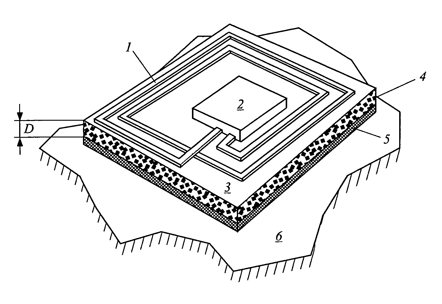
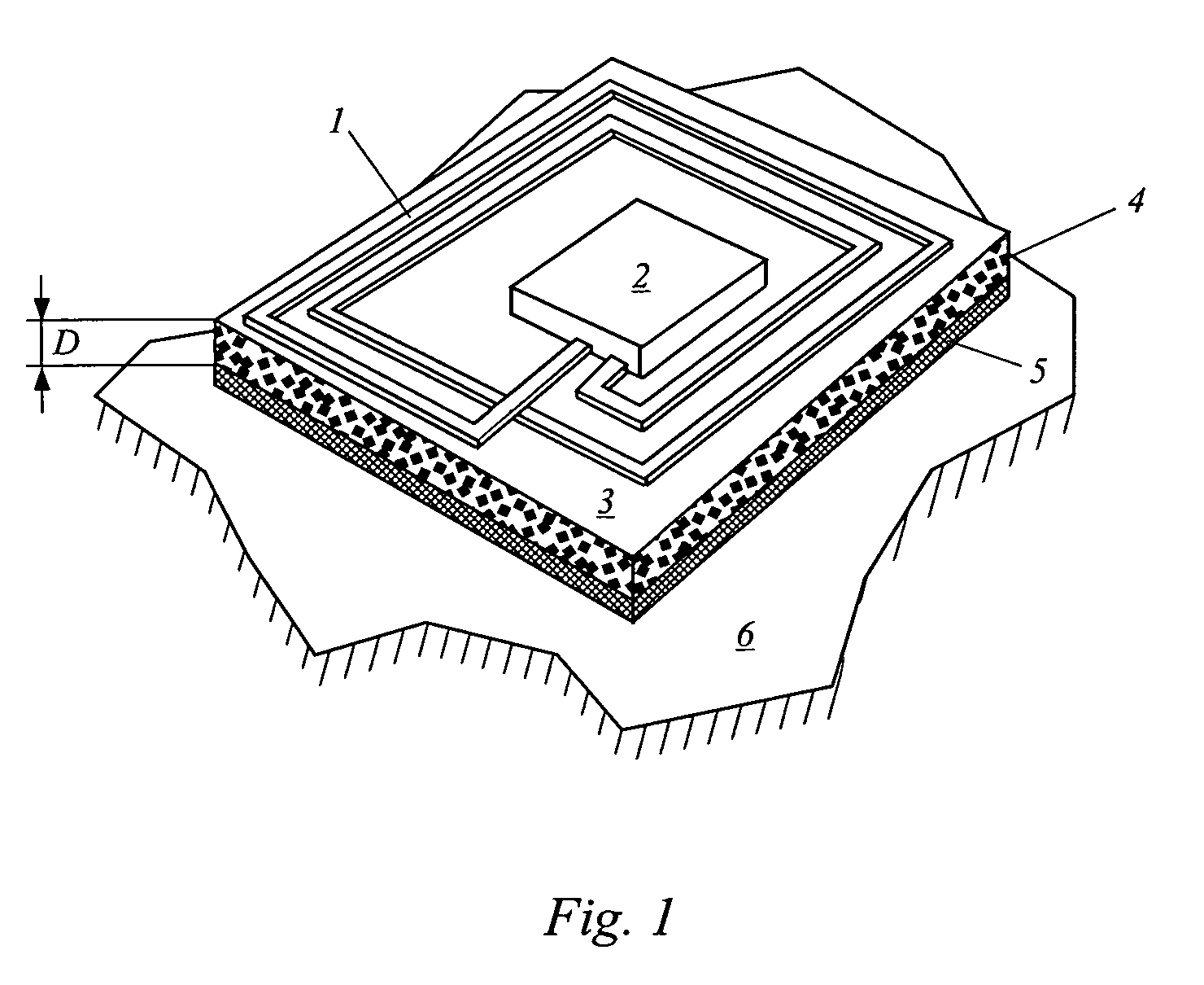
[0019]The transponder label shown in FIG. 1 has an antenna coil 1, a semiconductor chip 2, as well as a single-layer film 3 with the thickness D, which serves as a support film, for one, and for another, as a protection against the induction magnetic counter field in the metallic substrate 6, which affects a weakening of the oscillating magnetic field required for the transponder scanning.

[0020]The semiconductor chip 2 fulfills the function of a condenser element of the transponder resonance circuit, as well as the function of a storage component, on which specific data of the product are stored, a part of which represents the metallic substrate 6. The specific data, for example, can be a product code, a serial number, or the technical properties characterizing the product.

[0021]The film 3 comprises a flexible matrix, for example, silicon rubber, in which ferrite particles 4 are embedded, which bestow soft magnetic qualities on the film 3 and therewith are responsible for its shield...


PUM


Abstract

A transponder label includes an antenna coil, a semiconductor chip, and a single layer film, which acts both as a carrier film and as a shield against the induction of counter magnetic fields in the metallic base layer. The semiconductor chip acts both as a capacitor element of the transponder resonant circuit and as a memory component. The film is a flexible matrix including embedded ferrite particles, which give the film soft magnetic characteristics. The permeability value of the film is adapted to its thickness and the material of the base layer, the value being higher for a reduced thickness. The resonant frequency of the transponder resonant circuit formed from the antenna coil and semiconductor chip lies within a narrow target frequency range, once the label has adhered.

Description

CROSS REFERENCE TO RELATED APPLICATIONS[0001]Applicants claim priority under 35 U.S.C. §119 of German Application No. 102 04 884.3 filed on Feb. 6, 2002. Applicants also claim priority under 35 U.S.C. §365 of PCT / EP03 / 00205 filed on Jan. 11, 2003. The international application under PCT article 21(2) was not published in English.BACKGROUND OF THE INVENTION[0002]1. Field of the Invention[0003]The present invention relates to a transponder label.[0004]2. The Prior Art[0005]Transponder labels, generally also called RFID labels, which have a resonant circuit with a coil element and a condenser element, which can be shifted into resonance in a radio frequency range in order to detect the label, and, likewise also to supply a semiconductor chip mounted on the label with energy, are widely distributed. They are used, among other things, for the protection of goods and in many other applications, above all, in the field of logistics. In addition to the pure detection of the labels or the go...

Claims


Application Information

Patent Timeline
IPC IPC(8): G08B13/14G06K19/077
CPCG06K19/07749G06K19/07771
Inventor SURKAU, REINHARD
Owner SCHREINER GRP GMBH & CO KG
Why Eureka
Try Eureka