
Method for generating gas plasma

a plasma and gas technology, applied in plasma technology, electric discharge lamps, final product manufacturing, etc., can solve the problems of insufficient energy application to the gas particles in the tube b, damage to the substrate position in the chamber and the inside of the chamber, and increase manufacturing costs. , to achieve the effect of improving the plasma generation efficiency, reducing the cost of gas composition

Inactive Publication Date: 2007-03-20
SAMSUNG ELECTRONICS CO LTD
View PDF25 Cites 30 Cited by
  • Summary
  • Abstract
  • Description
  • Claims
  • Application Information

AI Technical Summary

Benefits of technology

This approach improves plasma generation efficiency, reduces manufacturing costs, and minimizes the use of expensive gases like NF3, while effectively etching semiconductor materials with enhanced productivity and reduced environmental footprint.

Problems solved by technology

Utilizing the in-situ process, a substrate positioned in the chamber and the inside of the chamber may be damaged because the plasma is directly generated in the chamber.
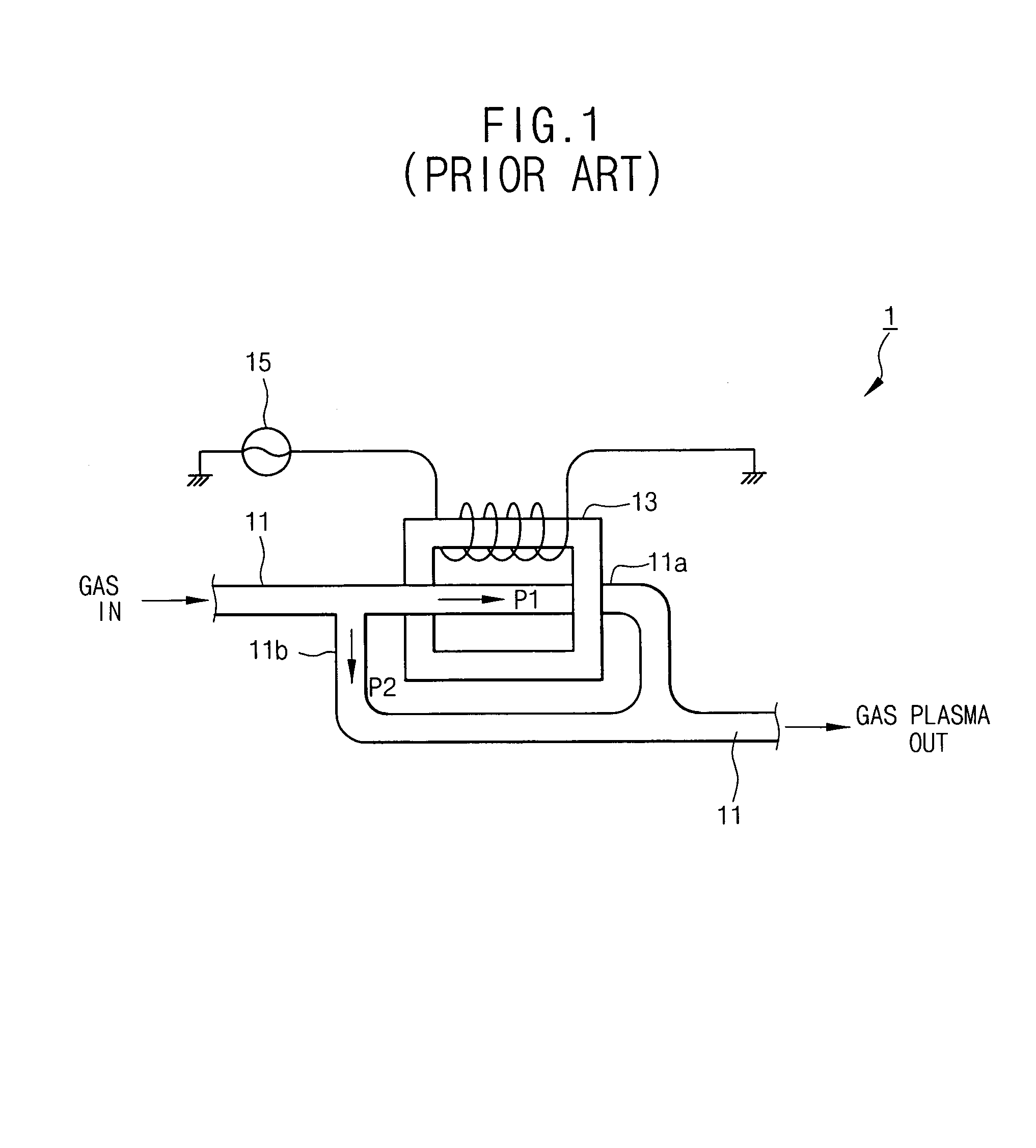
When the induction electric field is employed, the energy cannot be sufficiently applied to the gas particles in the tube 11 due to power loss.
However, the manufacturing cost may greatly increase when the plasma generating apparatus consumes the gas on a massive scale.
However, NF3 gas is expensive, so the manufacturing cost of the semiconductor device may increase.

Method used


Image

  • Method for generating gas plasma
  • Method for generating gas plasma
  • Method for generating gas plasma

Examples


example 1

[0119]In an exemplary embodiment, a processing gas including C3F8 gas at a flow rate of approximately 400 sccm, oxygen gas at a flow rate of approximately 1,000 sccm, and argon gas at a flow rate of approximately 2,000 sccm, was introduced into the remote plasma generating device shown in FIG. 6. Then, a plasma was generated from the processing gas in the plasma generating device under a pressure of approximately 0.7 Torr with a power of approximately 5,600 Watts.

example 2

[0120]In yet another exemplary embodiment, after a processing gas including C3F8 gas, is introduced at a flow rate of approximately 600 sccm, oxygen gas is introduced at a flow rate of approximately 1,800 sccm, and argon gas is introduced at a flow rate of approximately 4,000 sccm, into the remote plasma generating device shown in FIG. 6. A plasma was generated from the processing gas in the plasma generating device under a pressure of approximately 1.1 Torr with a power of approximately 6,400 Watts.

example 3

[0121]In another exemplary embodiment, a plasma was generated in the same manner as in Example 2 except that the pressure was approximately 1.5 Torr.


PUM


Abstract

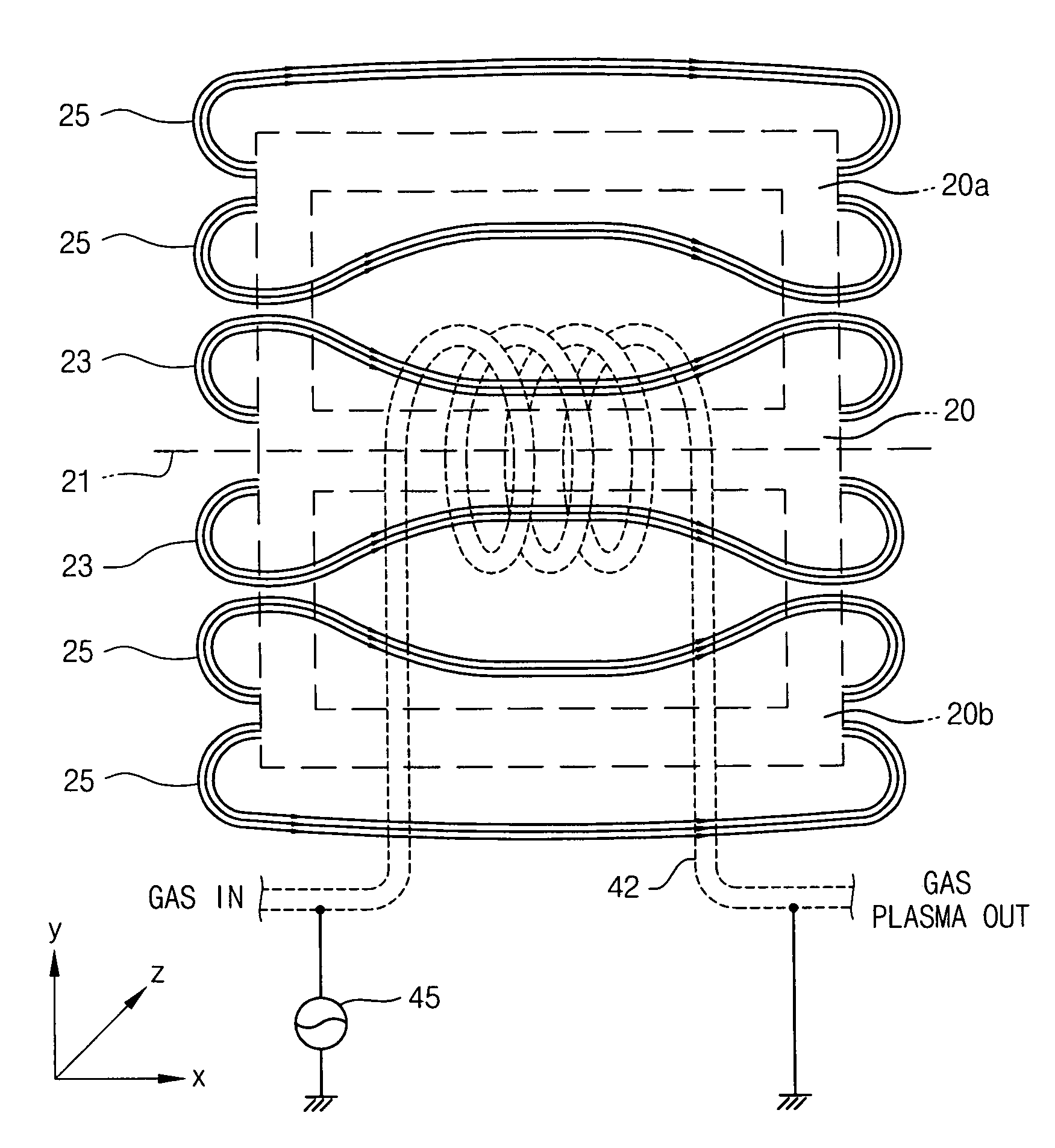
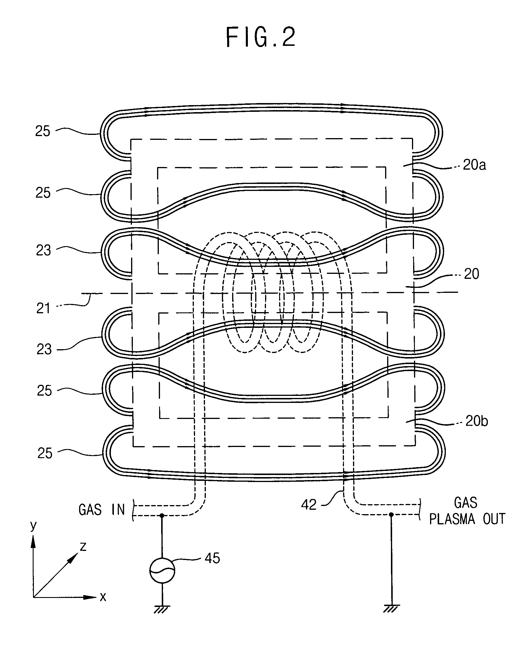
A method for generating a plasma. A gas flows along a flow path having the displacement identical to the lines of magnetic force of the main magnetic field, and high frequency alternating current is applied to the gas, thereby generating a gas plasma. For example, a gas is flowed through a pipe in a first direction. Electricity is conducted through the pipe in substantially the first direction. And a magnetic field is applied along a second direction (e.g., perpendicular to the first direction) to the gas flowing in the pipe such that a plasma is induced in the pipe.

Description

[0001]This U.S. nonprovisional patent application claims priority under 35 U.S.C. § 119 of Korean Patent Application 2002-69776 filed on Nov. 11, 2002, the entire contents of which are hereby incorporated by reference.BACKGROUND OF THE INVENTION[0002]1. Field of the Invention[0003]The present invention relates to generating a plasma using a gas composition for manufacturing a semiconductor device; more particularly, a method and an apparatus for generating a plasma using a remote process, a gas composition for generating the plasma to etch a layer, and a method for manufacturing a semiconductor device using the gas composition.[0004]2. Description of the Related Art[0005]Recently, semiconductor devices have been rapidly developed in order to meet various requirements of consumers and the development of information processing devices. The semiconductor devices are required to have high operation speed and large storage capacity. Thus, the semiconductor devices should be highly integr...

Claims


Application Information

Patent Timeline
Patent Type & Authority Patents(United States)
IPC IPC(8): H01J7/24H01L21/3065H01J37/32H01L21/311H05H1/30
CPCH01J37/321H01L21/31116H01J37/32357Y02C20/30Y02P70/50H05H1/30
Inventor MIN, YOUNG-MINCHOI, DAE-KYUBAE, DO-INYANG, YUN-SIKHWANG, WAN-GOOKIM, JIN-MAN
Owner SAMSUNG ELECTRONICS CO LTD
Learn More