
Methods and apparatus for measuring change in performance of ring oscillator circuit

a technology of ring oscillator circuit and measurement method, which is applied in the direction of pulse generator, pulse technique, instruments, etc., can solve the problems of no effective inline test that measures, and the performance of an integrated circuit may degrade by 5% or mor

Inactive Publication Date: 2007-03-13
IBM CORP
View PDF1 Cites 35 Cited by
  • Summary
  • Abstract
  • Description
  • Claims
  • Application Information

AI Technical Summary

Benefits of technology

The present invention provides techniques for testing the performance of a set of circuits after a short period of stress. This is done by measuring the difference in frequency between two identical circuits before and after applying stress. The change in beat frequency, which is a measure of the average performance of the circuits, is relatively insensitive to external factors and statistical variations. The invention also provides techniques for measuring the frequency of a ring oscillator circuit before and after an applied stress to determine the change in performance. The differential approach allows for a clean signal in response to a very short stress, and the configuration of the ring stages ensures that one stress mechanism dominates the circuit's response to stressing.

Problems solved by technology

Over the lifetime of an integrated circuit, the performance of an integrated circuit may degrade by 5% or more due to such effects.
Developing an understanding of the dependence of such degradation on processing techniques for each new technology is an important and difficult task, and may involve accelerated stress testing and comprehensive evaluation of large populations of devices, such as, for example, individual FETs.
Additionally, because stressing at room temperature makes it difficult to differentiate NBTI from hot electron effects, and because elevated temperatures are impractical inline, to date there have been no effective inline tests that measure NBTI and distinguish it from hot electron effects.

Method used


Image

  • Methods and apparatus for measuring change in performance of ring oscillator circuit
  • Methods and apparatus for measuring change in performance of ring oscillator circuit
  • Methods and apparatus for measuring change in performance of ring oscillator circuit

Examples


Embodiment Construction

[0019]As will be illustrated in detail below, the present invention introduces techniques for inline testing of stress induced performance degradation after a short stress period by measuring a change in frequency of a ring oscillator circuit.

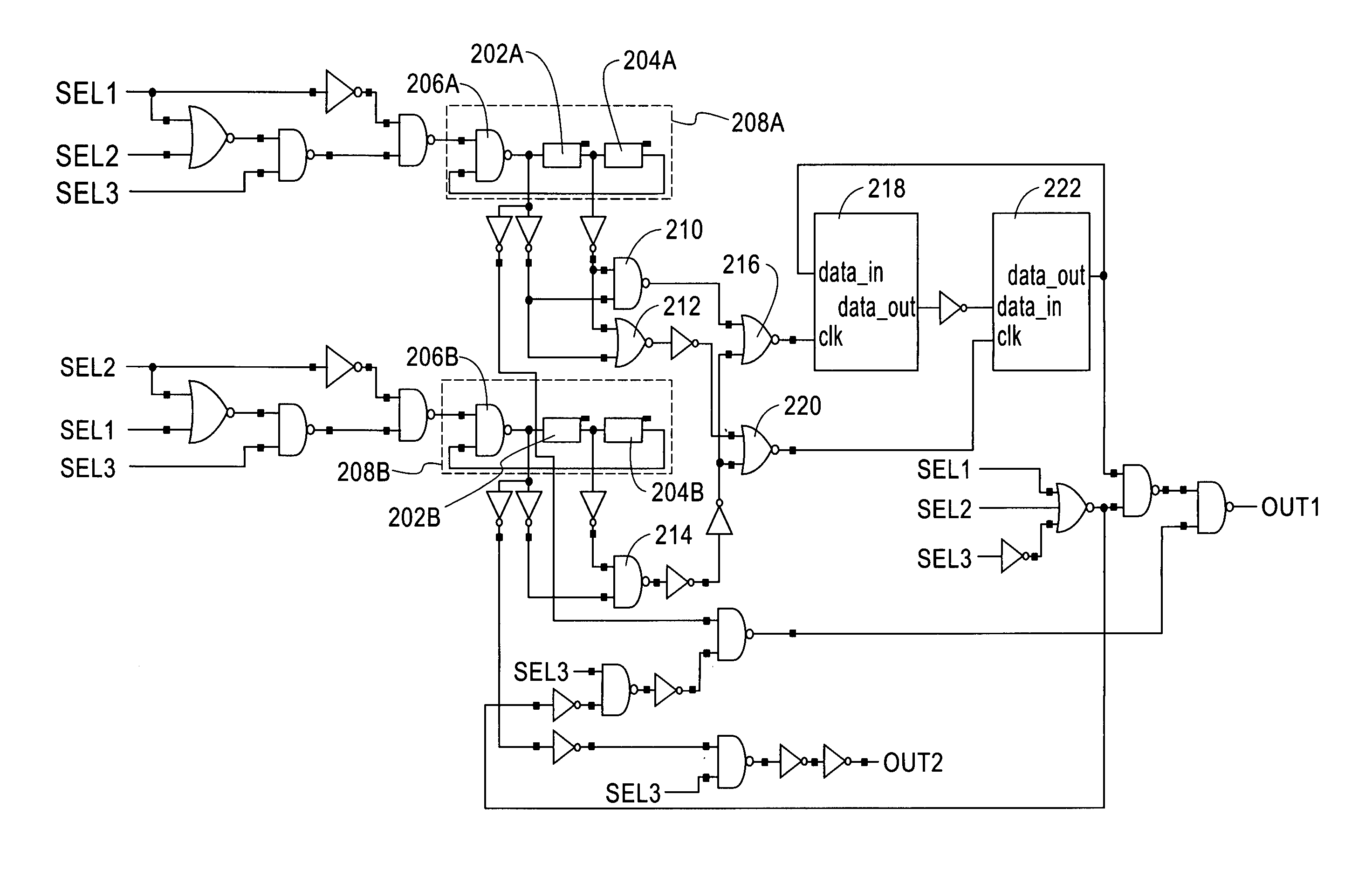
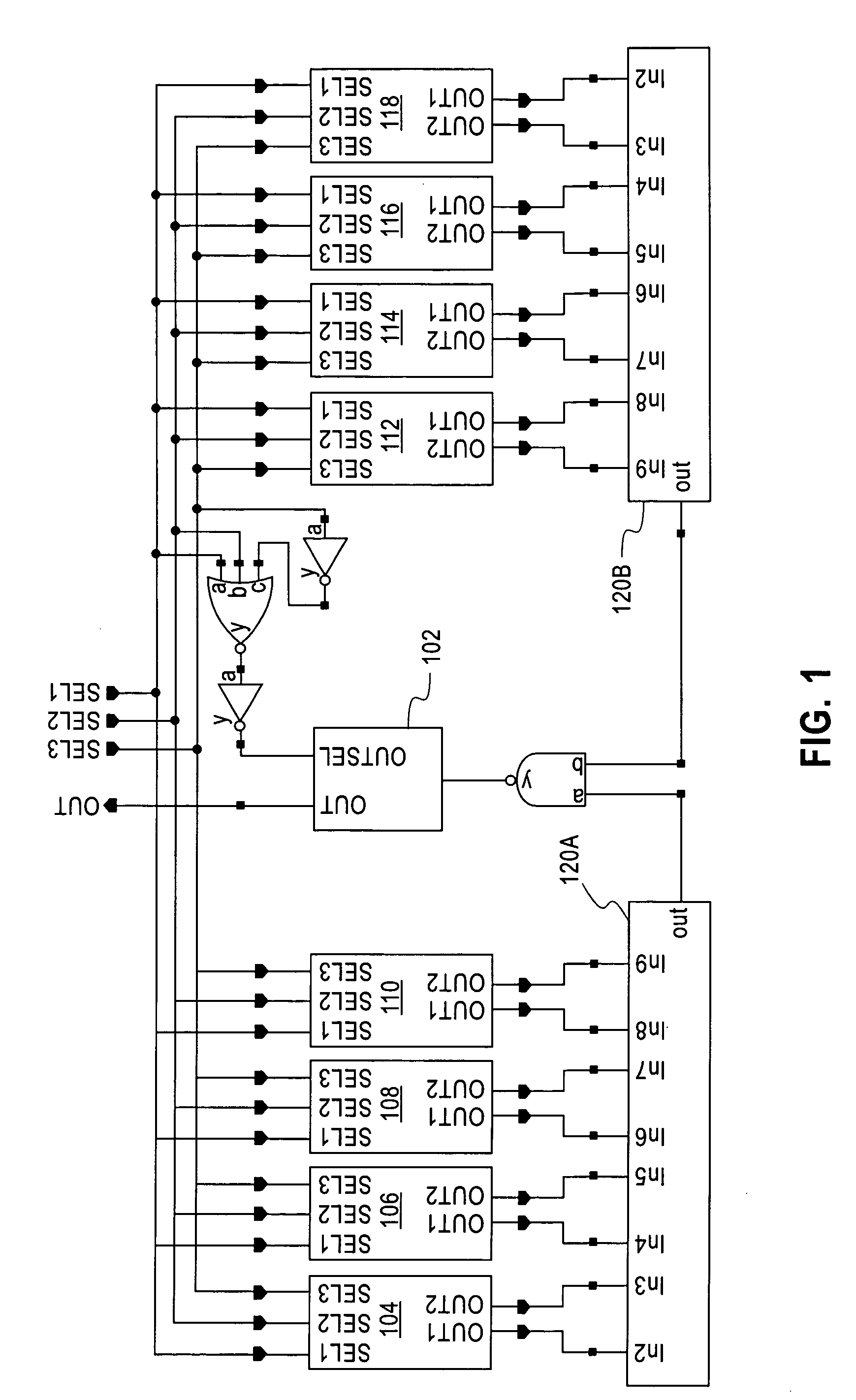
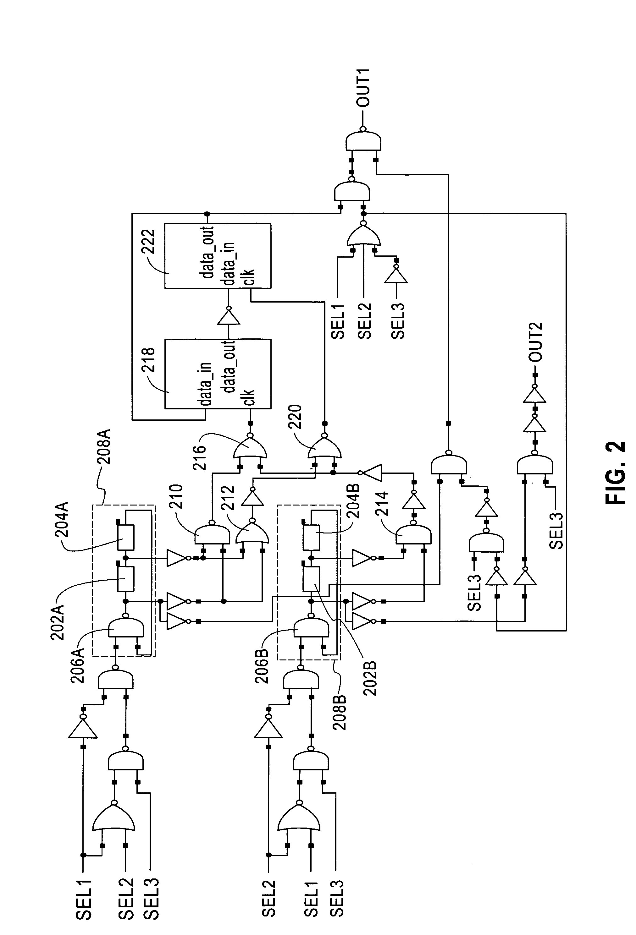
[0020]Referring initially to FIG. 1, a top level circuit diagram illustrates a circuit for inline measurement of ring oscillator circuit device frequency change, according to an embodiment of the present invention. Four pairs of ring oscillator circuits 104, 106, 108, 110 are disposed on a left side of a frequency divider 102, and four pairs of ring oscillator circuits 112, 114, 116, 118 are disposed on a right side of frequency divider 102. Each ring oscillator circuit may be powered independently via separate power supplies or separate I / O pads of a common power supply. The pairs of ring oscillator circuits may also be powered by a common power supply or pad. The pairs of ring oscillator circuits share common select circuitry, and control inp...


PUM


Abstract

An integrated circuit device is provided having one or more pairs of ring oscillator circuits. Each ring oscillator circuit of the one or more pairs of ring oscillator circuits is configured to connect to at least one voltage source capable of applying a stress to a ring oscillator circuit. One or more frequency measurement circuits are each electrically connected to a respective pair of the one or more pairs of ring oscillator circuits. Each frequency measurement circuit is configured to measure a stress induced change in frequency difference of the respective pair of the one or more pairs of ring oscillator circuits.

Description

FIELD OF THE INVENTION[0001]The present invention relates generally to integrated circuit devices and, more particularly, to inline techniques for measuring a change in performance of a ring oscillator circuit of an integrated circuit device caused by an applied stress.BACKGROUND OF THE INVENTION[0002]As scaling limits of complementary metal oxide semiconductor (CMOS) technology are neared, variability has been found to play an increasingly important role in integrated circuit performance. A change in performance of an integrated circuit over time may be caused by various stress mechanisms, such as, for example, hot electron effects in both negative channel field effect transistors (nFETs) and positive channel field effect transistors (pFETs), and negative bias temperature instability (NBTI) in pFETs. Over the lifetime of an integrated circuit, the performance of an integrated circuit may degrade by 5% or more due to such effects. In practice this anticipated future degradation may ...

Claims


Application Information

Patent Timeline
Patent Type & Authority Patents(United States)
IPC IPC(8): G01R23/00H03B5/24
CPCH03K3/0315G01R31/2824
Inventor BHUSHAN, MANJULKETCHEN, MARK B.
Owner IBM CORP
Learn More