Method and system for using optical phase conjugation in an optical communications network including an add/drop multiplexer

a technology of optical phase conjugation and optical communication network, applied in data switching networks, frequency-division multiplexes, instruments, etc., can solve problems such as inter-symbol interference and bit errors, additive non-linear effects can significantly impact the performance of wdm transmission systems, and deteriorate signal quality

Active Publication Date: 2007-02-27
CIENA
View PDF9 Cites 19 Cited by
  • Summary
  • Abstract
  • Description
  • Claims
  • Application Information

AI Technical Summary

Problems solved by technology

Since a bit contains many wavelengths traveling at different speeds, the bit tends to distort as it travels along the transmission fiber resulting in inter-symbol interference and bit errors.
Non-linear effects also induce crosstalk and deteriorate signal quality.
Accordingly, the additive non-linear effects can significantly impact performance of WDM transmission systems, particularly those over long distances, having multiple links, each including amplifiers.
While this technique of compensating dispersion does negate XPM and SPM effects in amplitude-modulated channels, it can cause resonance effects since all signals are compressed back to their start positions and are also all aligned in time (i.e., there is no time skew between signals).
A second complication of this solution that arises in multi-channel systems is the inability to perfectly match the dispersion slopes of the transmission fiber and dispersion compensating fiber.
A third problem with mitigating XPM and SPM effects with perfect per-link dispersion compensation is the distributed nature of SPM and XPM generation.
A fourth problem with mitigating SPM and XPM effects are non-overlapping dispersion optimization points for SPM compensation and XPM compensation.
For all these reasons, as transmission distances increase, it becomes more difficult to mitigate XPM and SPM generated noise by simple dispersion compensation or dispersion mapping.
None of the known techniques offers a solution that neutralizes non-linear effects that are present after all of the commonly used solutions are used.
A further complication in compensating for dispersion and non-linear effects is the deployment of optical add-drop multiplexers (OADMs) where WDM channels may be added and / or dropped.
This problem is further compounded by the fact that non-linear effects and dispersion are normally coupled, so dispersion compensation schemes affect signal distortions induced by non-linear effects and vice-versa.
Although such dispersion mapping is possible in theory, there may be instances where an average dispersion map may not yield acceptable Q-factor values for some OADM configurations resulting in either the system failing performance specifications or requiring use of more expensive technologies (e.g., per channel dispersion compensators) to meet performance specifications.
Even if expensive technologies are employed, system performance may still not be guaranteed due to fundamental non-linearity constraints.
Also, practical limitations (variability in link losses, link lengths, fiber types, dispersion compensation granularity and accuracy) make deploying theoretically good dispersion maps very difficult in real networks.

Method used


Image

  • Method and system for using optical phase conjugation in an optical communications network including an add/drop multiplexer
  • Method and system for using optical phase conjugation in an optical communications network including an add/drop multiplexer
  • Method and system for using optical phase conjugation in an optical communications network including an add/drop multiplexer

Examples


Embodiment Construction

[0031]The following detailed description of the invention refers to the accompanying drawings. The same reference numbers in different drawings identify the same or similar elements. Also, the following detailed description does not limit the invention. Instead, the scope of the invention is defined by the appended claims and equivalents thereof.

[0032]The expression “optically communicates” as used herein refers to any connection, coupling, link or the like by which optical signals carried by one optical system element are imparted to the “communicating” element. Such “optically communicating” devices are not necessarily directly connected to one another and may be separated by intermediate optical components or devices. Likewise, the expressions “connection” and “operative connection” as used herein are relative terms and do not require a direct physical connection.

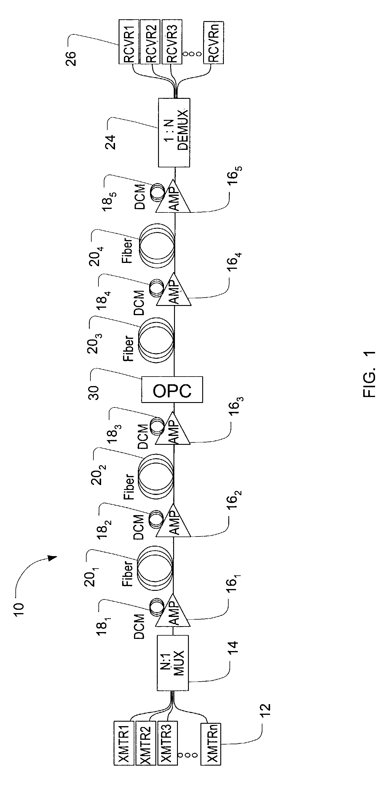
[0033]FIG. 1 depicts an optical communications network 10 in an exemplary embodiment of the invention. The network 10 ...


PUM


Abstract

A method and system for using optical phase conjugation in an optical communications network including an add-drop multiplexer. The method includes determining a position for an optical phase conjugator such that channel quality for a channel in improved above a threshold. Transmission characteristics such as amplifier launch power or dispersion features may be adjusted to compliment the optical phase conjugation. An alternate method includes positioning the optical phase conjugator to improve a weighted average channel quality for the network.

Description

CROSS-REFERENCE TO RELATED APPLICATIONS[0001]This application is a continuation-in-part of U.S. patent application Ser. No. 10 / 139,270, filed May 3, 2002, the entire contents of which are incorporated herein by reference.BACKGROUND OF THE INVENTION[0002]1. Field of Invention[0003]This invention relates to a method and system for using optical phase conjugation in an optical communications network.[0004]2. Description of Related Art[0005]Fiber-optic communication networks are experiencing rapidly increasing deployment. Especially rapid is the growth of segments that carry multi-gigabit digital data on multiple wavelengths over a single fiber strand, which are known as wavelength division multiplexing (WDM). The wavelength channel density (i.e., the number of channels carried by one fiber) and the data rate carried on individual wavelengths continue to increase. Current systems employ 50 GHz channel spacing, but 25 GHz and 12.5 GHz channel spacings are expected to be utilized. Data ra...

Claims


Application Information

Patent Timeline
IPC IPC(8): H04J1/16
CPCH04B10/25137H04J14/0221H04J14/0201
Inventor FRANKEL, MICHAEL Y.SARDESAI, HARSHAD P.
Owner CIENA
Why Eureka
Try Eureka