
Method for producing micromechanical structures and a micromechanical structure

a micromechanical and structure technology, applied in the direction of microstructural technology, microstructural devices, microstructural components, etc., to achieve the effect of improving the functionality of mechanical components, large sensor surfaces, and high resolution

Inactive Publication Date: 2007-02-13
ROBERT BOSCH GMBH
View PDF13 Cites 1 Cited by
  • Summary
  • Abstract
  • Description
  • Claims
  • Application Information

AI Technical Summary

Benefits of technology

[0004]The present invention is based on the object of improving the functionality of mechanical components in micromechanical systems, such as micromechanical systems especially in the use of SiGe technology, so that even producing comparatively large sensor surfaces, having a high resolution, is possible.
[0015]However, it is also possible to apply another layer onto the functional layer if the former only has stress behavior that corresponds to the surface barrier layer. Thereby the desired stress neutralization in the functional layer is then achieved. The production methods described have the advantage that thereby functional layers may be generated having comparatively low stress gradients under CMOS-compatible production conditions. The methods are comparatively robust with respect to fluctuations in the depositing parameters, since the stress gradient is not set via the germanium content, the pressure, the temperature of the doping concentration or even a gradient of these parameters. This makes carrying out the process extraordinarily simplified, particularly for batch processes, such as in an LPCVD oven depositing. At the same time, the depositing parameters may be chosen in such a way that the layers are deposited at a comparatively high rate, which is of advantage with regard to economical efficiency. Besides that, fewer test runs are required in establishing a manufacturing method, since manufacturing methods according to the present invention “function” in a large process window.

Problems solved by technology

What is common to all of them is that the sacrificial layer must really be removed totally or at least partially, since otherwise the surface barrier layer is not freely accessible, and then cannot be removed.

Method used


Image

  • Method for producing micromechanical structures and a micromechanical structure
  • Method for producing micromechanical structures and a micromechanical structure

Examples


Embodiment Construction

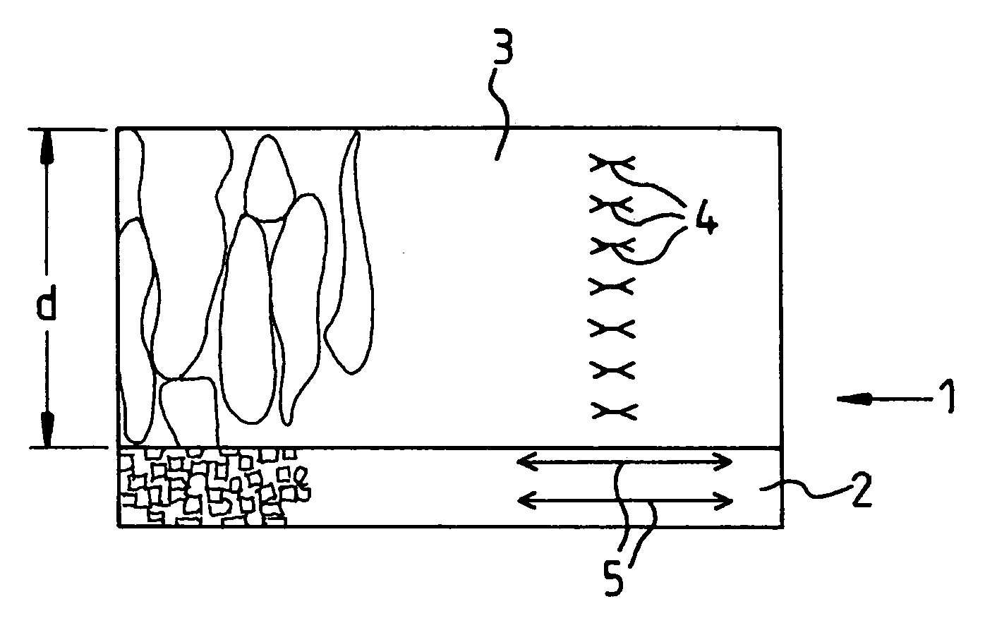
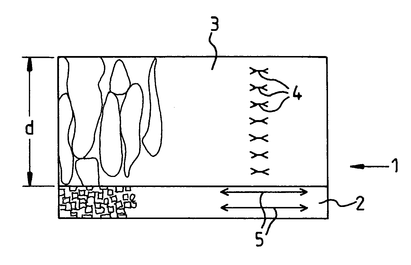
[0021]In a schematic cross section, the FIGURE shows a typical construction of an SiGe functional layer 1. Functional layer 1 has on its lower side a surface barrier layer 2, which is made up of amorphous or very small crystallites. Remaining functional layer 3 is next to surface barrier layer 2. Remaining functional layer 3 is made up of comparatively large crystallites, which to a great extent are uniform over the entire thickness of this layer. Therefore, this layer, as seen over its thickness d, has an essentially constant layer stress. The constant layer stress is either a comparatively slight tensile stress or compressive stress, which are symbolized by arrows 4 in layer 3.

[0022]By contrast, in surface barrier layer 2, a substantially greater compressive stress prevails (symbolized by arrows 5), with the result that the layer in the FIGURE bends up towards the top.

[0023]According to the present invention, only two types of thing can happen, then.

[0024]1. Either surface barrier...


PUM


Abstract

A method for producing micromechanical structures, in which a functional layer is deposited onto a sacrificial layer, and the sacrificial layer is removed again for the production of at least one mechanical functional element, which is characterized by a surface barrier layer, with which the functional layer begins on the sacrificial layer, and which has a different state from the remaining functional layer, is also removed at least to a considerable part, or, on the functional layer, one layer or a plurality of layers having at least approximately the same properties with respect to stress in the layer or layers such as the surface barrier layer is (are) applied. Additionally, a micromechanical structure having a functional layer in which the functional layer is constructed in such a way that the stresses are neutralized or no stress gradient appears.

Description

BACKGROUND INFORMATION[0001]Micromechanical systems may be produced based on multiple material combinations. The production may take place especially using the materials SiGe and Ge. In the case of integrated micromechanical systems, on a regular basis a combination is involved of electronic and mechanical components (e.g. resonators, acceleration sensors and yaw rate sensors). Onto the electronic components, as a rule, a printed circuit trace interconnect layer is applied to connect the mechanical and electronic components. Above that, there is a sacrificial layer, which, in SiGe technology is preferably made of Ge. On top of the sacrificial layer an SiGe functional layer is situated, of which the mechanical components are implemented.[0002]At present, the SiGe functional layer is mostly deposited using the LPCVD method (LPCVD standing for low pressure chemical vapor deposition). Other methods, which are also used, are epitaxial growth or PECVD (plasma enhanced chemical vapor depos...

Claims


Application Information

Patent Timeline
IPC IPC(8): H01L21/00B81B3/00
CPCB81B3/0072
Inventor FREY, WILHELMDUENN, CHRISTOPH
Owner ROBERT BOSCH GMBH
Learn More