Method of two dimensional feature model calibration and optimization

a feature model and optimization technology, applied in the field of photolithography, can solve the problems of reducing the size of the integrated circuit, reducing the resolution limit of the optical exposure tool, and becoming both a time-consuming and costly process, and achieving the effect of reducing the optical proximity

Inactive Publication Date: 2007-02-13
ASML NETHERLANDS BV
View PDF13 Cites 365 Cited by
  • Summary
  • Abstract
  • Description
  • Claims
  • Application Information

AI Technical Summary

Benefits of technology

[0019]In an effort to solve the aforementioned needs, it is an object of the present invention to provide an automated method of generating a set of optimized parameters (or calibration factors) using the printed 2D wafer patterns that define the printing performance of a given imaging system such that the parameters can be

Problems solved by technology

These rules are set by processing and design limitations.
As the size of an integrated circuit is reduced and its density increases, however, the CD of its corresponding mask pattern approaches the resolution limit of the optical exposure tool.
This trial and error process, which can entail repeated mask revisions followed by repeated simula

Method used


Image

  • Method of two dimensional feature model calibration and optimization
  • Method of two dimensional feature model calibration and optimization
  • Method of two dimensional feature model calibration and optimization

Examples


Embodiment Construction

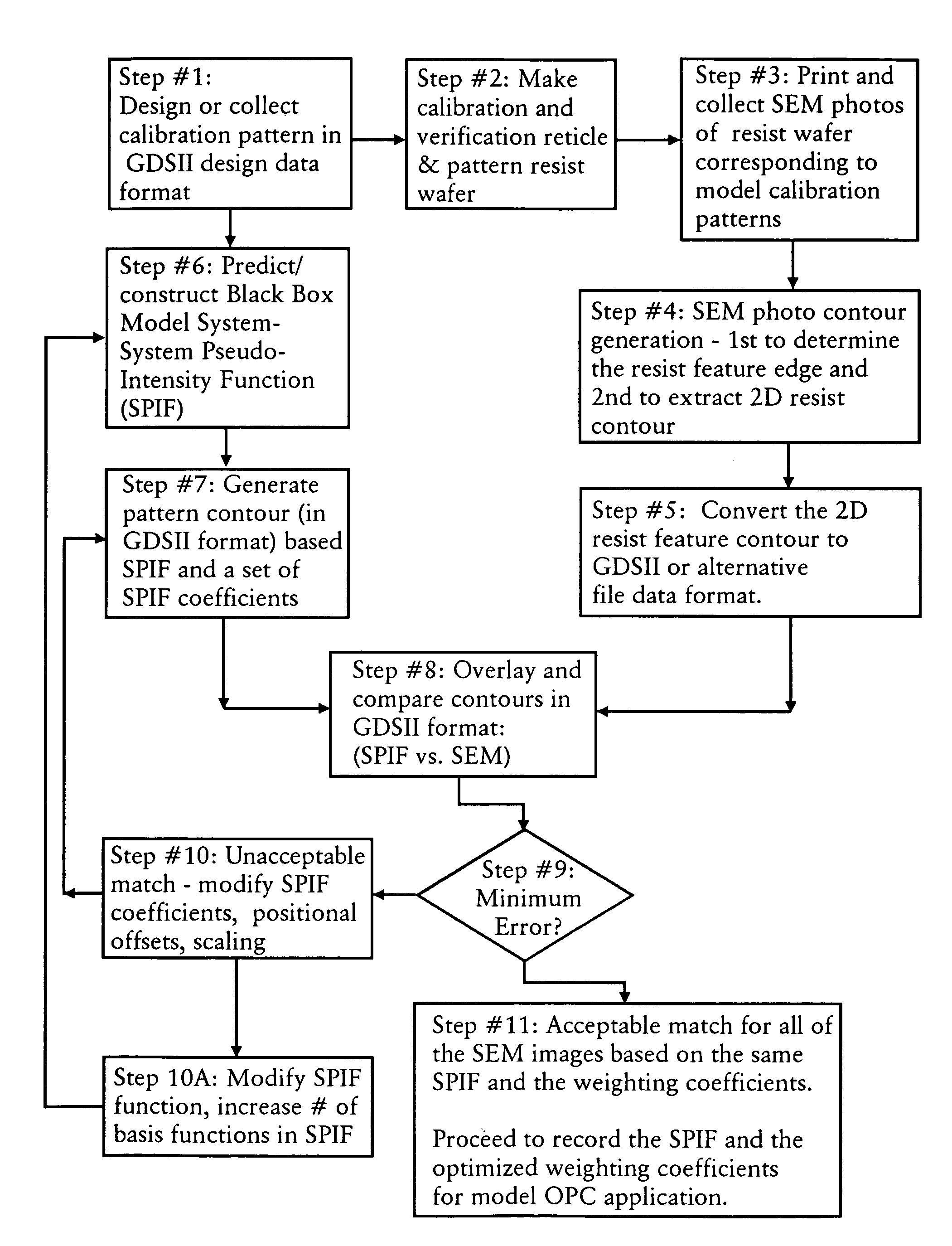
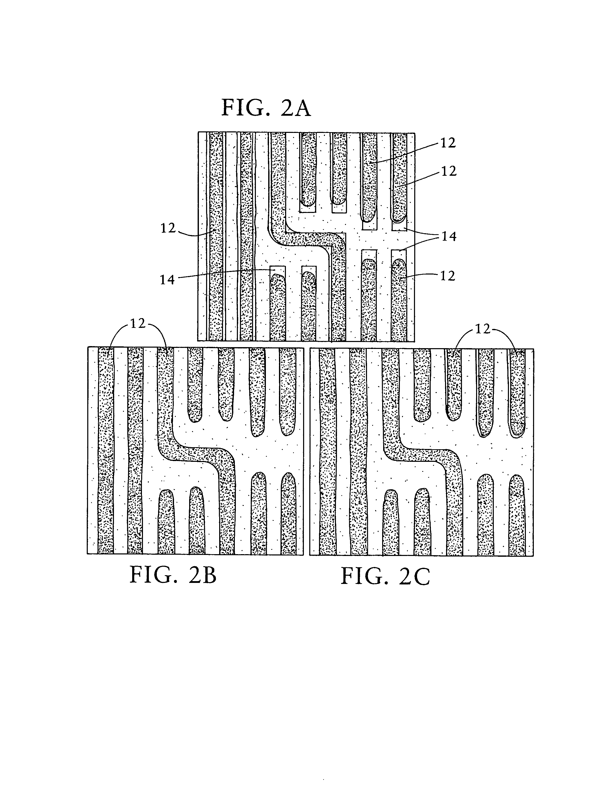
[0040]In accordance with the present invention, a method is disclosed for calibrating an imaging system by determining a set of performance parameters (i.e., calibration model) which define the printing performance of the given imaging system. The performance parameters are determined for multiple types of features that may be printed in a typical mask design (e.g., densely-spaced features, semi-isolated features, isolated features, line-ends, elbows, etc.). As explained in more detail below, the performance parameters are utilized to determine how a mask should be modified such that the desired feature is accurately printed on the wafer (i.e., the resulting resist pattern formed by the mask accurately corresponds to the desired feature).

[0041]Once the performance parameters (or calibrated model) have been determined for a sufficient number of features, the performance parameters are utilized to compensate for optical proximity errors occurring during photoresist printing (or after ...


PUM


Abstract

A method for generating a photolithography mask for optically transferring a pattern formed in the mask onto a substrate utilizing an imaging system. The method includes the steps of: (a) defining a set of calibration patterns, which are represented in a data format; (b) printing the calibration patterns on a substrate utilizing the given imaging system; (c) determining a first set of contour patterns corresponding to the calibration patterns imaged on the substrate; (d) generating a system pseudo-intensity function, which approximates the imaging performance of the imaging system; (e) determining a second set of contour patterns by utilizing the system pseudo-intensity function to define how the calibration patterns will be imaged in the substrate; (f) comparing the first set of contour patterns and the second set of contour patterns to determine the difference therebetween; (g) adjusting the system pseudo-intensity function until the difference between the first set of contour patterns and the second set of contour patterns is below a predefined criteria; and (h) utilizing the adjusted system pseudo-intensity function to modify the mask so as to provide for optical proximity correction.

Description

RELATED APPLICATIONS[0001]This application claims priority from U.S. Provisional Patent Application Ser. No. 60 / 327,302, filed Oct. 9, 2001, entitled METHOD FOR 2D PATTERN PROFILE CALIBRATION AND VERIFICATION WITH APPLICATION TO MODEL-BASED OPTICAL PROXIMITY CORRECTION.FIELD OF THE INVENTION[0002]The present invention generally relates to photolithography, and in particular to a method of generating a known set of functions (i.e., calibrated model) defining the performance of an imaging system which are subsequently utilized to correct for optical proximity effects and to improve the printing of mask patterns on substrates.[0003]The present invention also relates to the use of such a calibration technique in a lithographic projection apparatus, which generally comprises:[0004]a radiation system for supplying a projection beam of radiation;[0005]a support structure for supporting patterning means (e.g., mask), the patterning means serving to pattern the projection beam according to a...

Claims


Application Information

Patent Timeline
IPC IPC(8): G03F1/00G06F17/50G03F1/36G03F7/20H01L21/027
CPCG03F1/36G03F1/144G03F1/68G03F1/00G03F7/20
Inventor LAIDIG, THOMASCHEN, JANG FUNGSHI, XUELONGSCHLIEF, RALPHHOLLERBACH, UWEWAMPLER, KURT E.
Owner ASML NETHERLANDS BV
Why Eureka
Try Eureka