
Radio receiving apparatus and radio receiving method

a technology for receiving apparatus and radio receiving, applied in the direction of pulse technique, amplitude demodulation, line-fault/interference reduction, etc., can solve the problems of interference generation, no longer hold on the orthogonality between spreading codes, etc., to reduce the calculation amount, optimize the performance of interference cancellation, and prevent the effect of deterioration of rake combining performan

Inactive Publication Date: 2007-01-23
III HLDG 12 LLC
View PDF15 Cites 6 Cited by
  • Summary
  • Abstract
  • Description
  • Claims
  • Application Information

AI Technical Summary

Benefits of technology

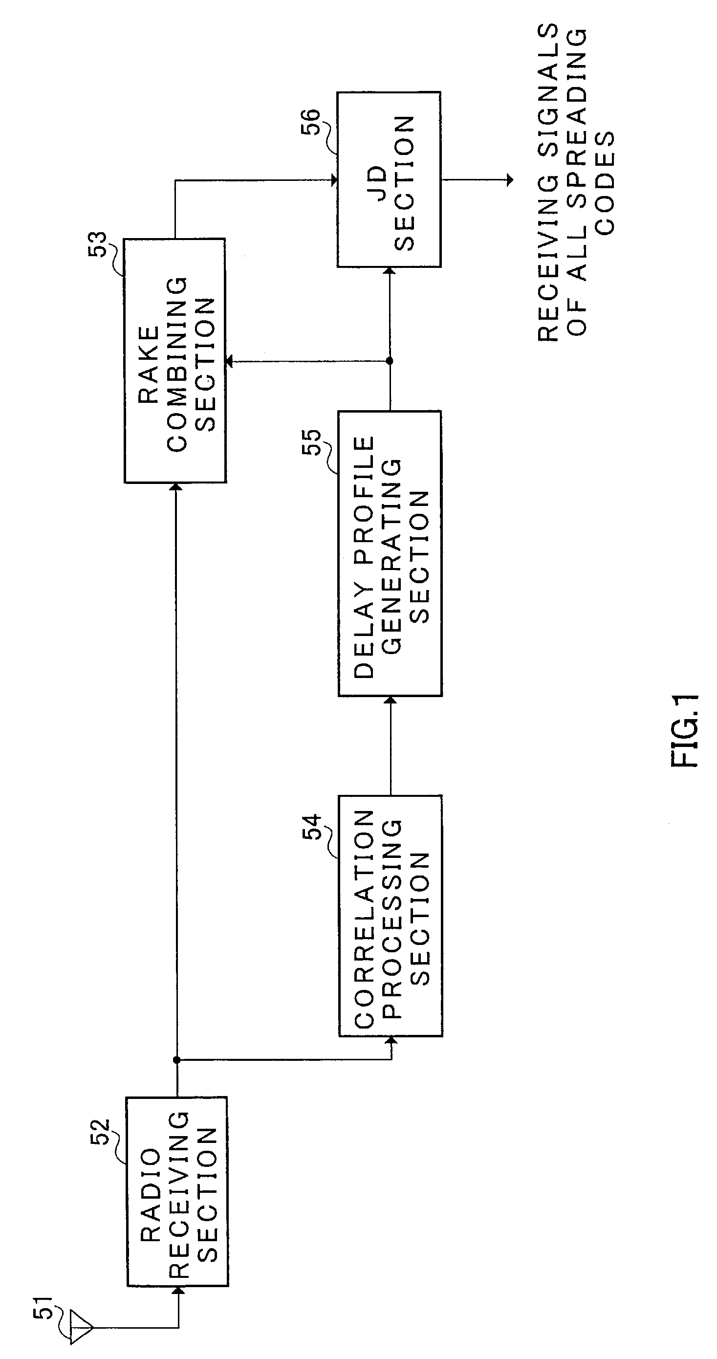
[0012]It is an object of the present invention to provide radio receiving apparatus and radio receiving method which are able not only to prevent deterioration of the RAKE combining performance, but also able to optimize the performance of interference cancellation and the calculation scale.
[0013]The inventors reach the present invention by focusing their attention on the existence of a plurality of delay waves that have small delay from the precedence signal and the existence of few delay waves which are largely separated from the precedence signal in radio communication under multipath environment, and reducing the calculation amount by cancelling peripheral multipath interferences of the precedence wave so that a sufficient performance is obtained.
[0014]In other words, such an object can be achieved by setting a delay time, which is shorter than the delay time used in RAKE combining, in a delay profile generated based on the known signal included in the receiving signal, within the range of this delay time, interference cancellation processing is performed on the signal after being RAKE combined so that the receiving signals of all codes are outputted, and carrying out a sufficient cancellation of the interference caused due to cross correlation between spreading codes while keeping the RAKE combining performance and reducing the operation scale of interference cancellation and amount of calculation.

Problems solved by technology

However, because there is a multipath in real propagation environments, the orthogonality between spreading codes is no longer hold and an interference is generated when multiplexing (code multiplexing) and transmitting a plurality of spreading codes.

Method used


Image

  • Radio receiving apparatus and radio receiving method
  • Radio receiving apparatus and radio receiving method
  • Radio receiving apparatus and radio receiving method

Examples


embodiment 1

(Embodiment 1)

[0023]In the present embodiment, maximum delay time setting using delay spread of receiving signal together with the case when obtaining receiving signal after performing interference cancellation using such a maximum delay time will be explained.

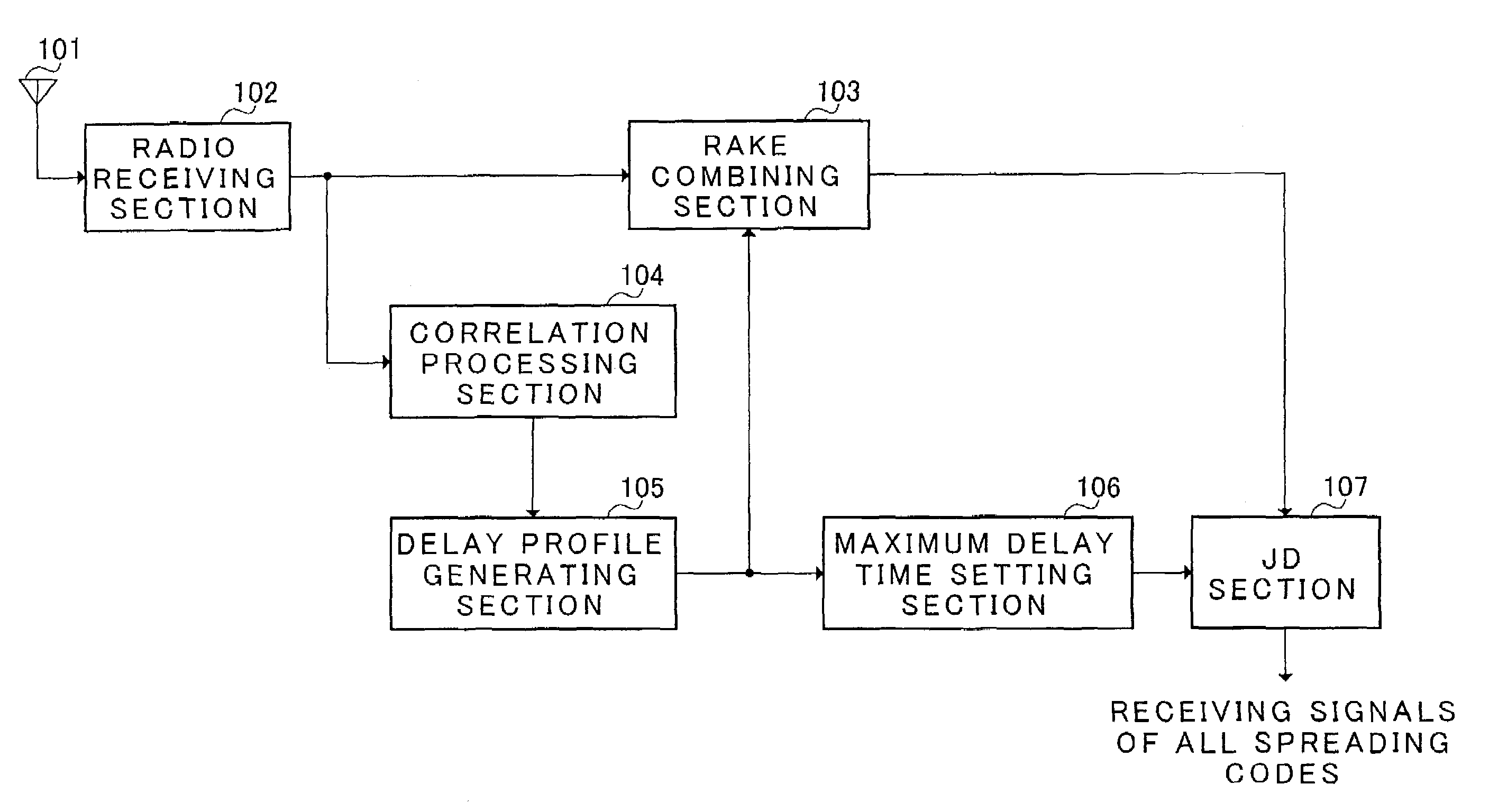
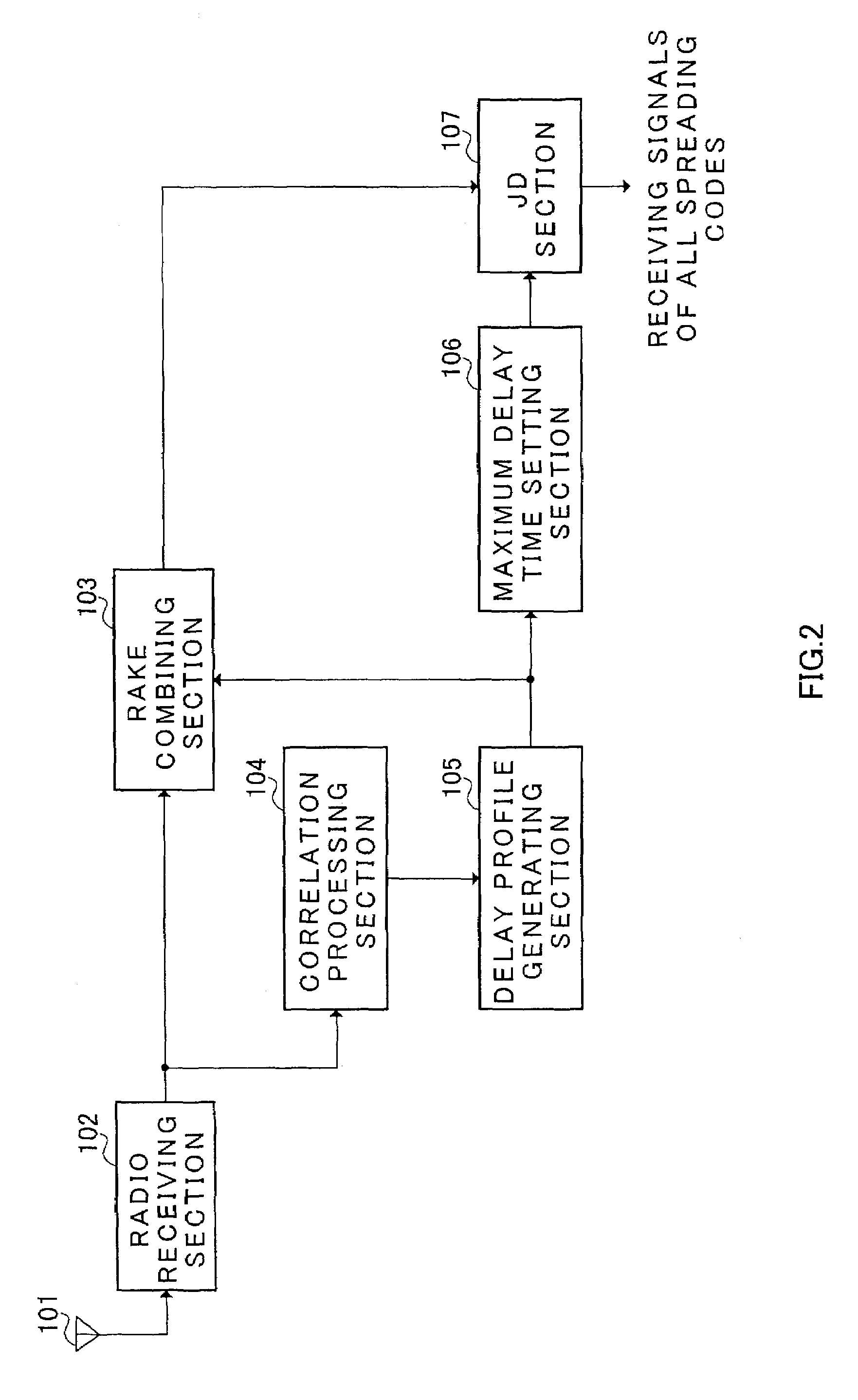
[0024]FIG. 2 is a block diagram showing a configuration of a radio receiving apparatus according to Embodiment 1 of the present invention, and FIG. 3 is a block diagram showing a configuration of a maximum delay time setting section included in radio receiving apparatus according to Embodiment 1 of the present invention.

[0025]A radio signal is received in radio receiving section 102 via antenna 101. In radio receiving section 102, predetermined radio reception processing (such as, down conversion, A / D conversion, etc.) are performed on the received signal, and the signal being subjected to radio reception processing is outputted to RAKE combining section 103 and correlation processing section 104.

[0026]In correlation processin...

embodiment 2

(Embodiment 2)

[0048]In the present embodiment, a maximum delay time is set by carrying out threshold value decision on the correlation value resulted from calculating the convolution of the delay profile of spreading codes, and the case when outputting receiving signal after performing interference cancellation using such a maximum delay time will be explained.

[0049]FIG. 7 is a block diagram showing a configuration of maximum delay time setting section included in radio receiving apparatus according to Embodiment 2 of the present invention.

[0050]In FIG. 7, maximum delay time setting section 106 comprises spreading code selecting section 1063 to select a set of spreading codes to be convoluted with delay profile, convolution calculating section 1064 to calculate cross correlation from the result of convolution calculation between the selected spreading codes and the delay profile, and threshold value deciding section 1065 to carry out threshold value decision as compared to cross cor...


PUM


Abstract

In maximum delay time setting section 106, a delay time width W′ used for cancelling the interference is set using the delay profile. In the present embodiment, delay spread is calculated and a delay wave included in the delay spread is set as W′. First, the delay spread is calculated in delay spread calculating section 1061 of maximum delay time setting section 106. That is to say, the standard deviation of the delay profile is calculated. The calculated delay spread is outputted to maximum delay time determining section 1062. The maximum delay time (window width) W′ is determined in maximum delay time determining section 1062 based on the delay spread. Therefore, the delay wave included in the maximum delay time which is determined by such a way is set to be an object of interference cancellation in joint detection. Thus, besides interference cancellation performance, optimization of calculation scale can be planned without losing performance of RAKE combining.

Description

TECHNICAL FIELD[0001]The present invention relates to a radio receiving apparatus and radio receiving method employed in a digital radio communication system.BACKGROUND ART[0002]In digital radio communication system, CDMA (Code Division Multiple Access) as a multiple access method takes benefits of the orthogonality between spreading codes, resulting in no interference due to cross correlation between spreading codes, thus, a plurality of spreading codes can be multiplexed and transmitted.[0003]However, because there is a multipath in real propagation environments, the orthogonality between spreading codes is no longer hold and an interference is generated when multiplexing (code multiplexing) and transmitting a plurality of spreading codes. In CDMA, RAKE combining is employed and effective advantages were shown when using RAKE combining in which a plurality of paths are combined in multipath propagation environments encountered a large interference deterioration.[0004]Several metho...

Claims


Application Information

Patent Timeline
Patent Type & Authority Patents(United States)
IPC IPC(8): H03D1/04H04B1/00H04B1/707H04B1/7105
CPCH04B1/7105H04B1/7115H04B1/7113
Inventor NISHIO, AKIHIKOHIRAMATSU, KATSUHIKO
Owner III HLDG 12 LLC
Learn More