Pulse output circuit, shift register, and display device
a shift register and output circuit technology, applied in the direction of logic circuit coupling/interface arrangement, pulse technique, instruments, etc., can solve the problems of difficult to effectively reduce the manufacturing cost of such display devices, source region and drain region cannot be discriminated from each other, etc., to achieve low cost and reduce the number of manufacturing steps
- Summary
- Abstract
- Description
- Claims
- Application Information
AI Technical Summary
Benefits of technology
Problems solved by technology
Method used
Image
Examples
embodiment 1
[0144]FIG. 3A shows an example of a shift register arranged in such a manner that a scanning direction inverting function is added to the shift register described above in the description of the embodiment mode of the present invention. The shift register of this embodiment uses additional input signals: an input change signal (LR) and an inverted input change signal (RL) other than those used in the circuit shown in FIG. 1A.
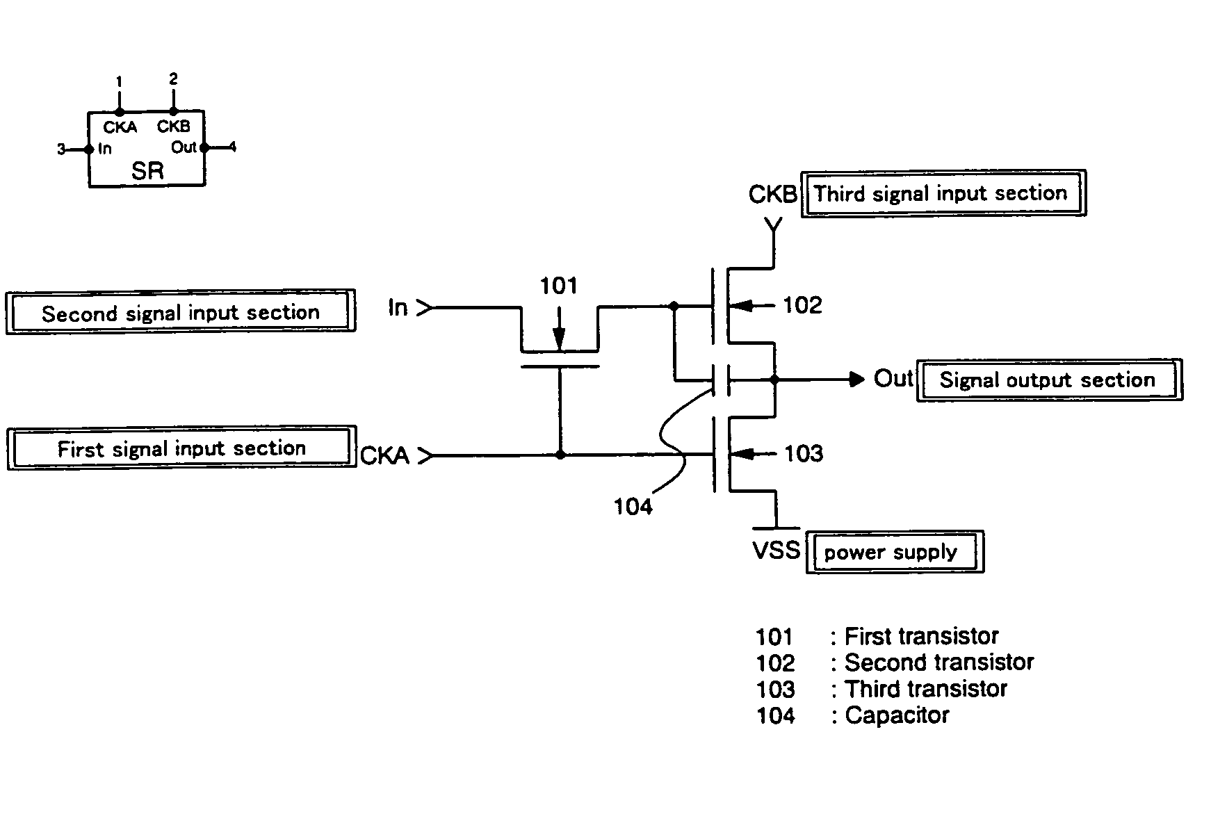
[0145]FIG. 3B shows details of the configuration of the pulse output circuit corresponding to one stage represented by a block 300 in FIG. 3A. The portion of the pulse output circuit constituted by TFTs 301 to 303 and a capacitor 304 is the same as the circuit shown in FIG. 1B, and the pulse output circuit of this embodiment has an input change circuit 310 constituted by a switch formed of TFTs 305 and 306, a fifth signal input section, and a sixth signal input section.
[0146]Each of output electrodes of TFTs 305 and 306 is connected to an input electrode of TFT ...
embodiment 2
[0150]An example of a display device fabricated by using only TFTs of one polarity will be described.
[0151]FIG. 12 is a diagram schematically showing the entire display device. A source signal line driver circuit 1201, a gate signal line driver circuit 1202, and a pixel portion 1203 are formed integrally with each other on a substrate 1200. A section of the pixel portion 1203 shown in a frame 1210 indicated by the dotted line is a segment for forming one pixel. The example of the pixel shown in FIG. 12 is a pixel of a liquid crystal display device. ON / OFF control of each pixel is performed by using one TFT in the pixel (hereinafter referred to as “pixel TFT”) when charge is applied to one electrode of the liquid crystal device. Signals (clock signals, a start pulse, etc.) for driving the source signal line driver circuit 1201 and the gate signal line driver circuit 1202 are externally supplied via a flexible printed circuit (FPC) 1204.
[0152]The substrate having the pixel TFT and the...
embodiment 3
[0175]In the embodiment mode of the present invention and the above embodiments of the present invention, examples of the circuits formed by using only n-channel TFTs have been shown. However, similar circuits may be formed by using only p-channel TFTs and by interchanging the power supply potential levels.
[0176]FIGS. 13A and 13B illustrate an example of a shift register formed by using only p-channel TFTs. The structure shown in the block diagram of FIG. 13A is the same as that of the shift register shown in FIGS. 1A and 1B, which is formed by using only n-channel TFTs. A block 1300 in FIG. 13A represents a pulse output circuit forming one stage for outputting a sampling pulse. The shift register shown in FIG. 13A differs from the shift register formed by using only n-channel TFTs in that the levels of the power supply potentials are reversed as shown in FIG. 13B.
[0177]FIG. 14 shows a timing chart and output pulses. The operation of each section is the same as that in the embodimen...
PUM
 Abstract
Description
Claims
Application Information
 - R&D
- Intellectual Property
- Life Sciences
- Materials
- Tech Scout
- Unparalleled Data Quality
- Higher Quality Content
- 60% Fewer Hallucinations
Browse by: Latest US Patents, China's latest patents, Technical Efficacy Thesaurus, Application Domain, Technology Topic, Popular Technical Reports.
© 2025 PatSnap. All rights reserved.Legal|Privacy policy|Modern Slavery Act Transparency Statement|Sitemap|About US| Contact US: help@patsnap.com


