
Analyzer for measuring multiple gases

Inactive Publication Date: 2006-12-19
ADVANCED FUEL RES INC
View PDF4 Cites 9 Cited by
  • Summary
  • Abstract
  • Description
  • Claims
  • Application Information

AI Technical Summary

Benefits of technology

[0015]Additional objects of the invention are to provide such a system that is relatively compact, incomplex, inexpensive, and convenient to construct and employ, and to provide such a method that is relatively fast, convenient and effective to perform.
[0026]Since the electric current through the sensor is proportionally dependent upon the number of oxygen ions pumped across the electrolyte, and since the amount of oxygen diffusing through the barrier is related to the pressure of oxygen in the gas sample, the current output can be calibrated for the oxygen partial pressure; at low oxygen partial pressures, the relationship between the oxygen partial pressure and the output current is linear. In addition to enabling ready measurement of oxygen concentrations in a volume of gas, moreover, the limiting current sensor described is advantageous in requiring no reference gas and also in being available in the form of a miniature, low-cost package (about $100) and with a self-heating feature.

Problems solved by technology

Despite the foregoing and other advantages, FT-IR technology is widely recognized to be deficient for multigas analysis applications because of one limitation.
In addition to being of a size that is still relatively large, however (as compared to a stand-alone FT-IR system), and to entailing relatively high levels of sampling complexity and cost, traditional analyzers with which an FT-IR system might be coupled (e.g., chemical cells, paramagnetic cells, and laser / optical cells used for measuring oxygen) often entail the significant disadvantage of requiring moisture removal from the gas streams being analyzed.
Because they require external heating and the use of a reference gas, however, and provide only a logarithmic output, such potentiometric sensors are regarded to be unsuitable for oxygen-measuring applications to which this invention is addressed.
Traditional hydrogen sensors (e.g., chemical cells such as catalytic bead sensors, semiconductor sensors, electrochemical sensors, resistive palladium alloy sensors, and field effect transistors) also entail significant disadvantages.
For example, they tend to be inordinately expensive, to be susceptible to poisoning or chemical irreversibility, and to afford relatively slow response times.

Method used


Image

  • Analyzer for measuring multiple gases
  • Analyzer for measuring multiple gases
  • Analyzer for measuring multiple gases

Examples


Embodiment Construction

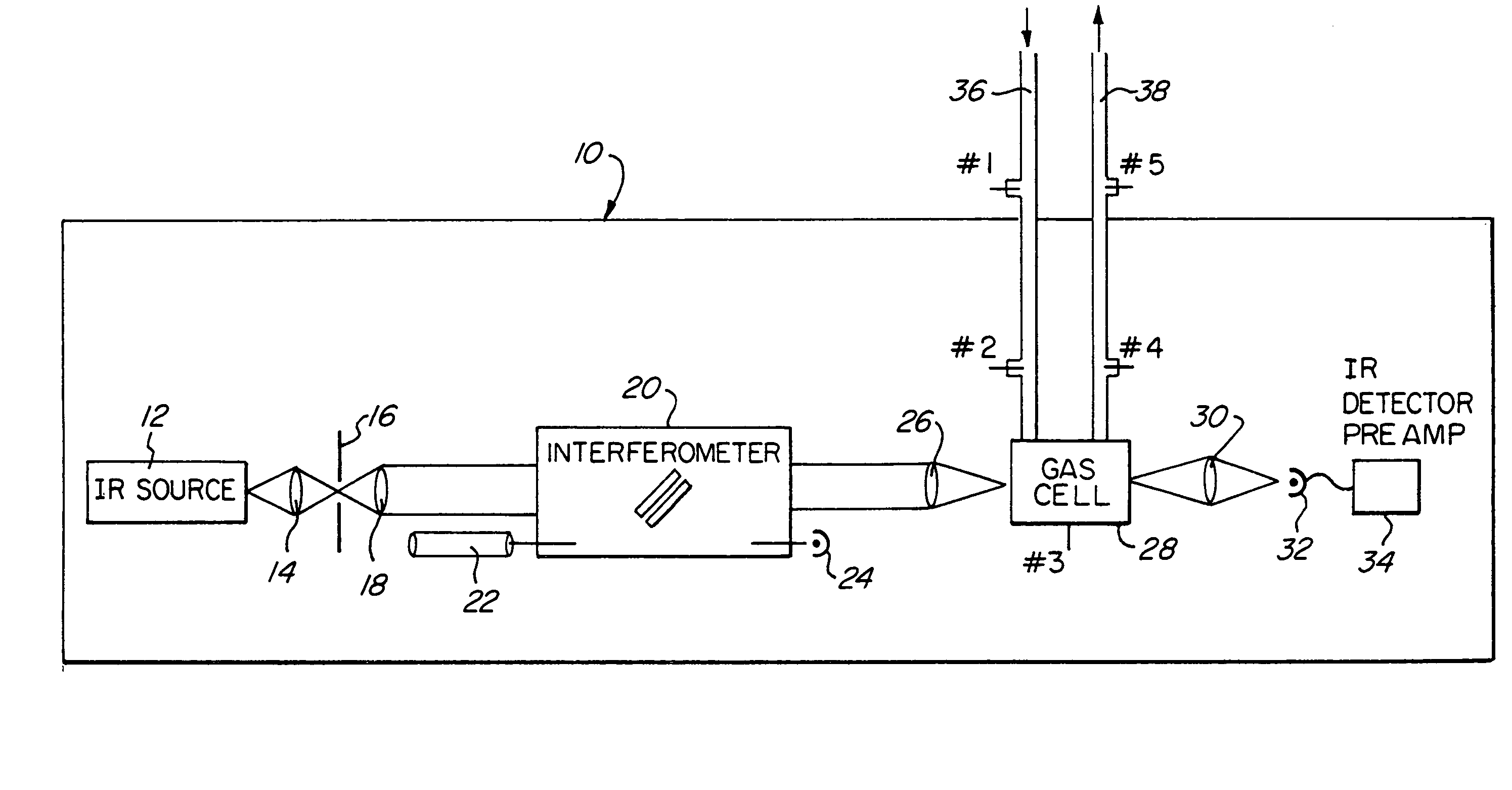
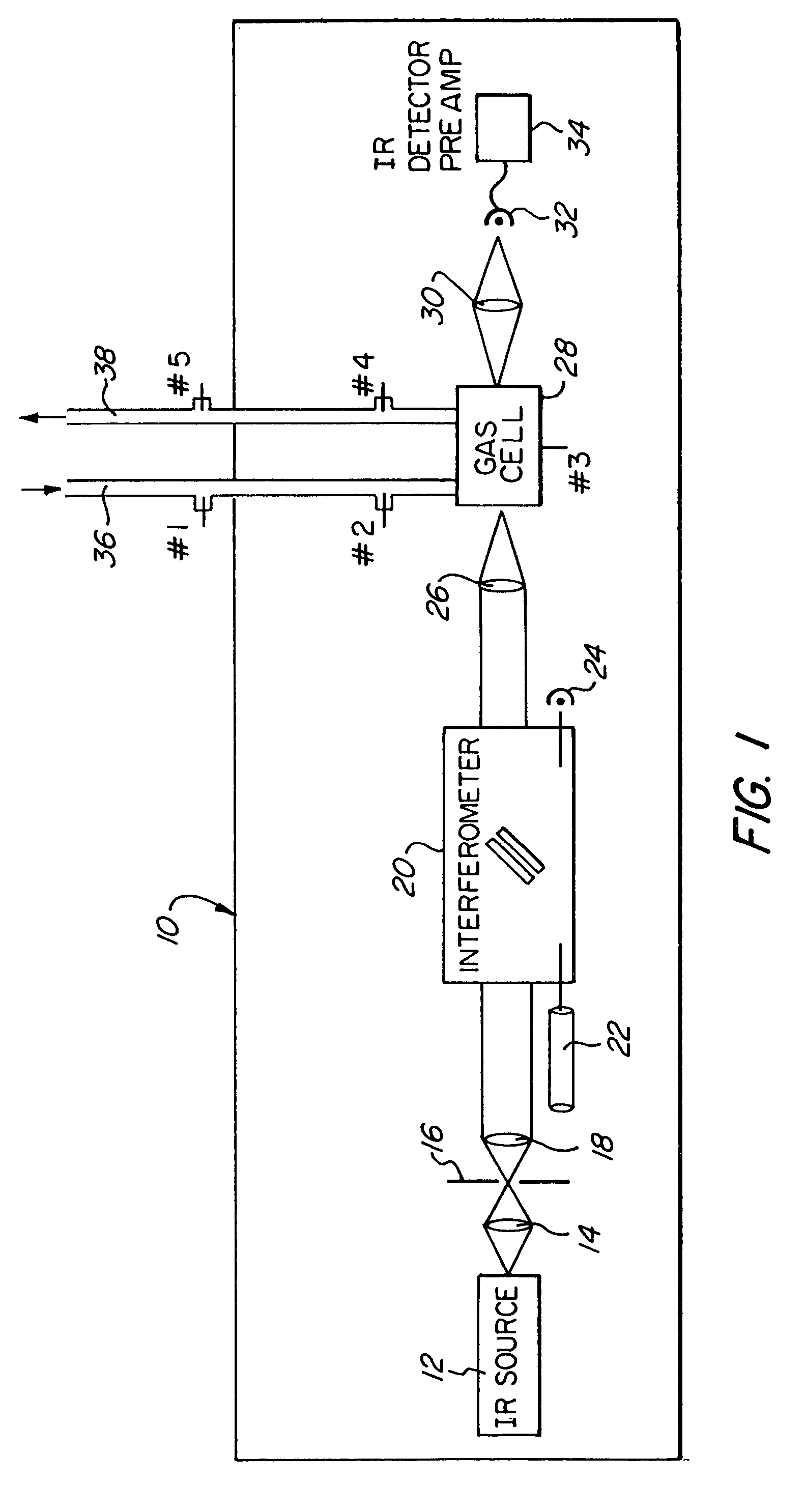
[0039]As seen in FIG. 1, the system of the invention comprises conventional components of an FT-IR gas analyzer contained in a product case, generally designated by the numeral 10. An infrared source 12 projects a beam of radiation sequentially through collection optics 14, a Jacquinot stop 16, and collimation optics 18 to an interferometer 20, the latter being fitted with a laser and a laser detector 22 and 24, respectively. The beam exiting the interferometer 20 passes through collection optics 26 to a gas cell 28, and thereafter through optics 30 to an infrared detector 32, the latter having an associated preamp 34.

[0040]Gas entry and exit conduits, or tubes, 36 and 38, lead respectively into and from the FT-IR product gas cell 28. Five suitable locations for the limiting current-type oxygen sensor, employed in the embodiment here described, are indicated and are designated #1 through #5. Specifically, the oxygen sensor may be disposed in the sample inlet transfer tube 36 at loca...


PUM


Abstract

Stand-alone multiple gas analysis apparatus, of relatively small physical size, integrates one or more supplemental sensors, such as a self-heating, amperometric, limiting current-type oxygen sensor and / or a titania nanotube-type hydrogen sensor, into the sampling cell gas flow components of an FT-IR gas analyzer. The apparatus enables simultaneous quantitative concentration measurements of infrared-active gases and of infrared-inactive atomic species and homonuclear diatomic molecules, such as of oxygen and hydrogen.

Description

CROSS-REFERENCE TO RELATED APPLICATION[0001]This application claims the benefit of U.S. Provisional Patent Application No. 60 / 451,484, filed Mar. 3, 2003 in the names of the same inventors.STATEMENT OF GOVERNMENT INTEREST[0002]The United States Government has rights in this invention under Air Force Contract No. F40600-02-C-0018.BACKGROUND OF THE INVENTION[0003]The measurement of gaseous molecules by Fourier transform infrared (FT-IR) spectroscopy is well known in the art. FT-IR gas analysis is a full spectroscopic technique that makes it possible to monitor many species simultaneously, using a single instrument. It is based on the fact that every gaseous molecule, with the exception of homonuclear diatomics, has a unique set of rotational and vibrational frequencies that absorb and emit infrared energy in a characteristic manner. In general, gases can be identified and quantified based upon the spectral location and magnitude of those absorptions, which occur throughout much of the...

Claims


Application Information

Patent Timeline
IPC IPC(8): G01J5/02G01N21/35
CPCG01N21/3504G01N2021/3595
Inventor MARKHAM, JAMES R.BONZANI, JR., PETER J.
Owner ADVANCED FUEL RES INC
Learn More