Eureka AIR delivers breakthrough ideas for toughest innovation challenges, trusted by R&D personnel around the world.

Method for producing a container from a thermoplastic film, and molding tool for executing the method

a thermoplastic film and container technology, applied in the direction of dough shaping, baking, domestic articles, etc., can solve the problems of low wear on moving parts, and achieve the effect of reliably into the stacking device, high cycle number, and high quality

Inactive Publication Date: 2006-11-28
ADOLF ILLIG MASCHENBAU
View PDF7 Cites 17 Cited by
  • Summary
  • Abstract
  • Description
  • Claims
  • Application Information

AI Technical Summary

Benefits of technology

"The invention is a method for producing containers with a hollow floor or bottom and a completely-sealed standing base. The method allows for the molding of containers with relatively large undercuts and conical regions. The method also minimizes wear on the parts forming the hollow floor and is applicable in multiple-row molding tools. The method involves clamping a segment of plastic film, deforming it by differential pressure, and creating a space between the inside surface of the standing base and the outside surface of the mold floor to allow the container to be ejected from the lower tool part. The method ensures that the container bottom is cooled intensively and can be securely held in a stacking device until it is stacked. The invention also includes a molding tool with a compressed-air supply, a lower tool part with a blank punch and shaping parts, an inwardly directed pinched edge, an axially displaceable mold floor, and an axially displaceable sealing bell. The method can be implemented with a combination molding and punching tool or a subsequent punching tool."

Problems solved by technology

Because the components forming the hollow floor only execute an axial movement, and are not acted upon by lateral forces, the moving parts are subjected to low wear.

Method used


Image

  • Method for producing a container from a thermoplastic film, and molding tool for executing the method
  • Method for producing a container from a thermoplastic film, and molding tool for executing the method
  • Method for producing a container from a thermoplastic film, and molding tool for executing the method

Examples


Embodiment Construction

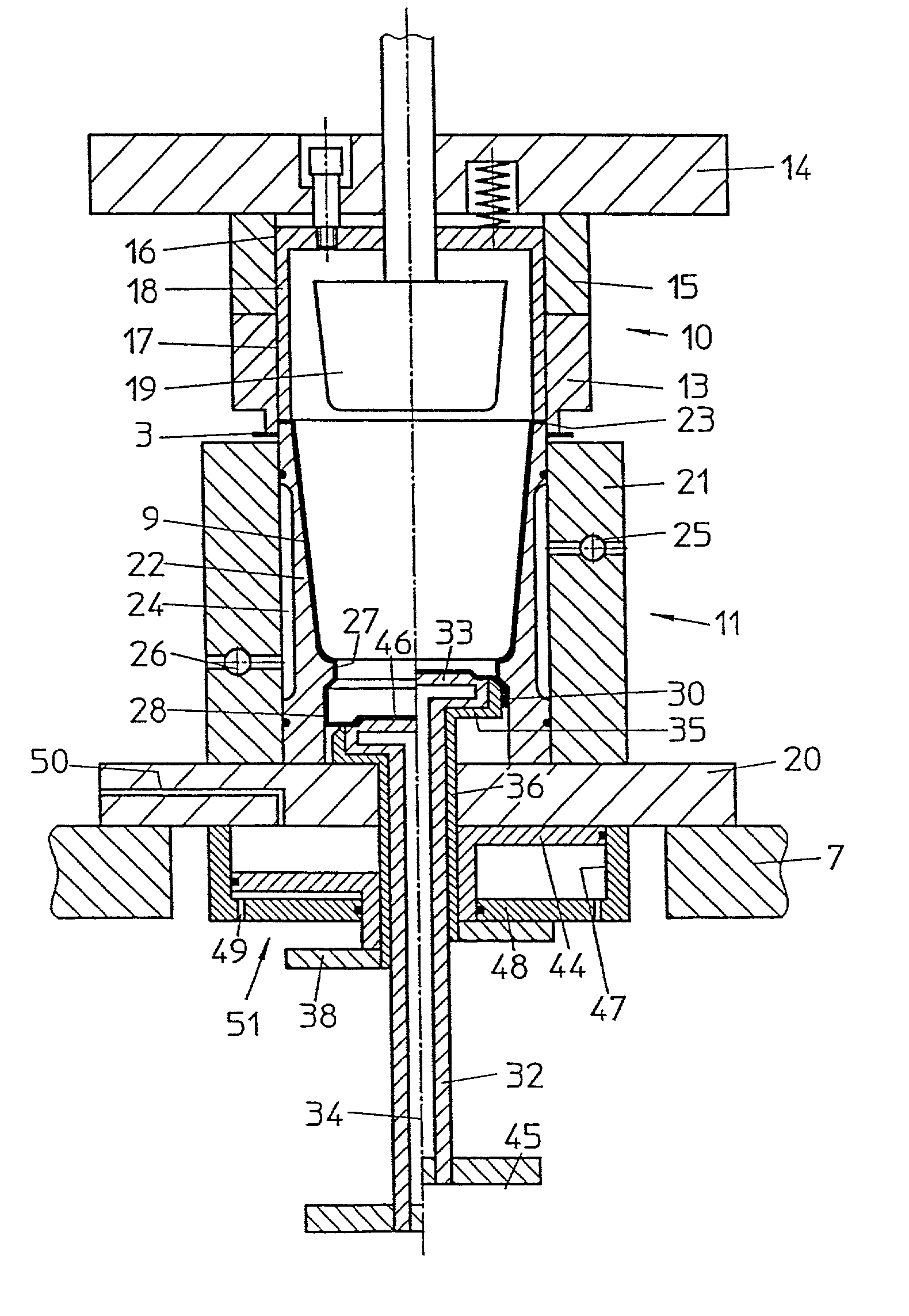
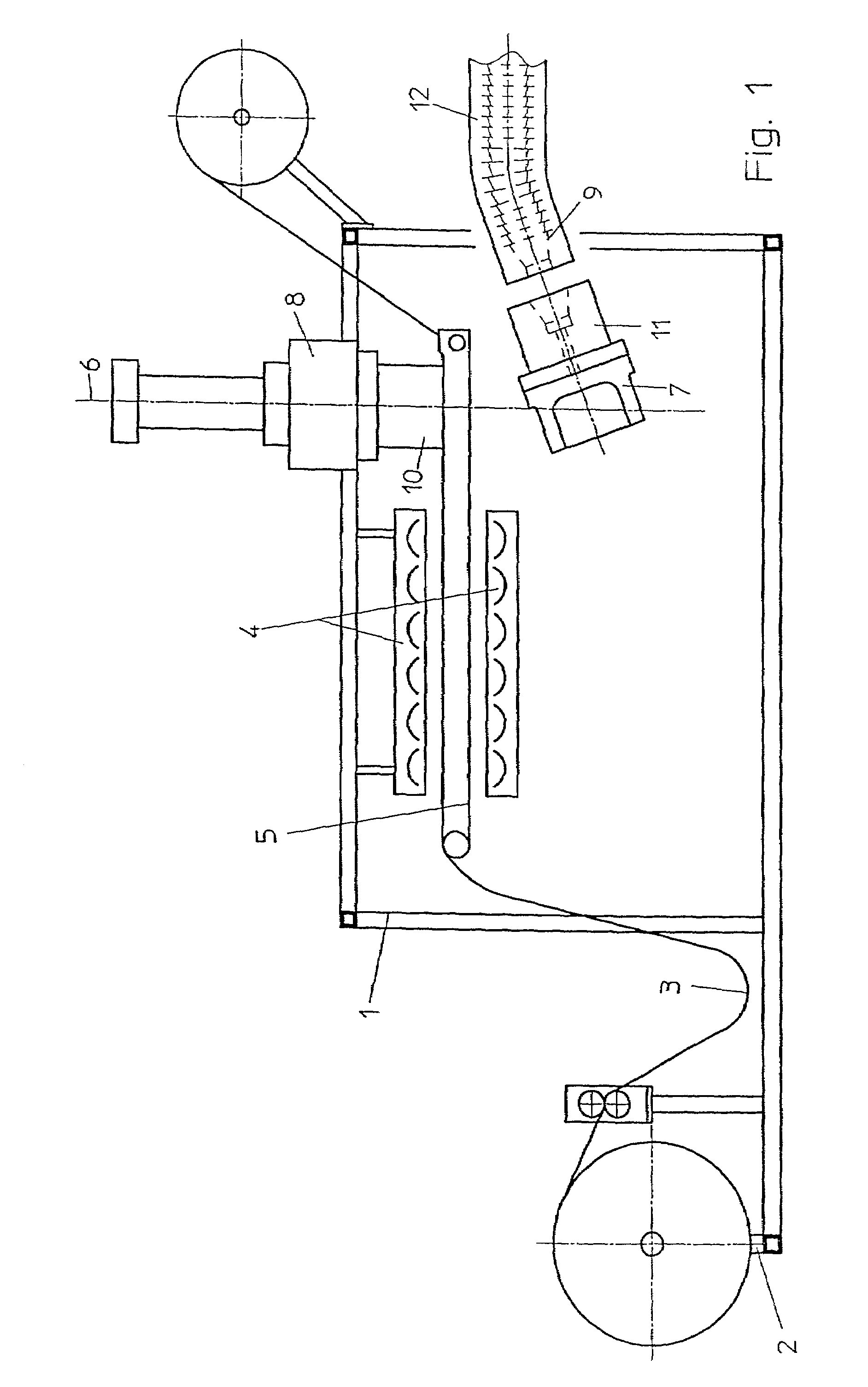
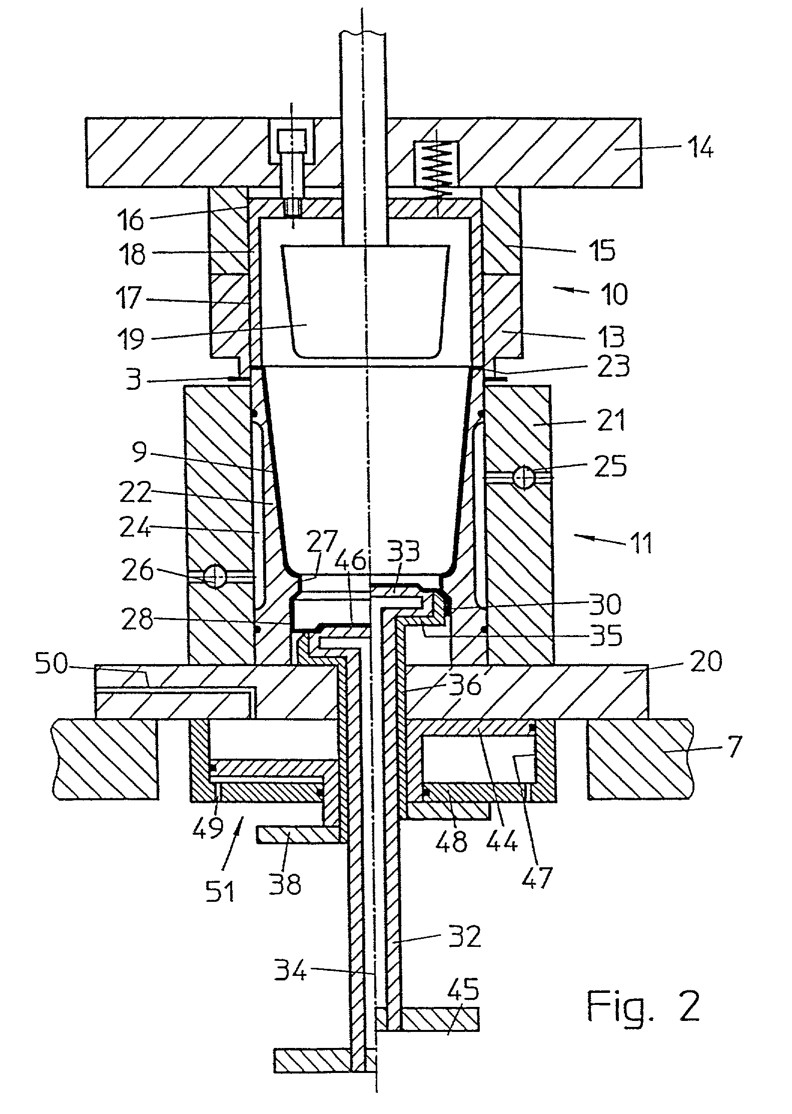
[0023]The essential components of the thermoforming machine are accommodated in a stand 1, into which the molding tool for executing the method is installed. A roller receptacle 2 provided on the input side is omitted if the thermoplastic plastic film 3 to be shaped is supplied directly from an extruder. The heating device 4 also may not be necessary if the extruder is directly connected. An intermittently-operated transport device 5 guides the plastic film 3 to a molding station 6 having a lower table 7 and an upper table 8. In this station, 6 compressed air or a vacuum serves in shaping and punching out containers 9 with the molding tool, which comprises an upper mold part 10 and a lower mold part 11. After the molding table 7 has been lowered and possibly pivoted with the lower mold part 11, which gives the containers 9 their shape, the containers are ejected into stacking grooves 12 or transferred to appropriate downstream devices.

[0024]FIG. 2 illustrates the design of the moldi...


PUM

PropertyMeasurementUnit
diameteraaaaaaaaaa
thicknessaaaaaaaaaa
displacementaaaaaaaaaa

Abstract

A method and a molding tool for producing containers from a thermoplastic plastic film. The method and tool permit the production of containers having a hollow floor and a double-walled standing base, with a seal between the two walls of the standing base. The method permits the production of such a container in large piece numbers, and with a high quality, and allows it to be transferred reliably into a stacking device. The components of the molding tool are subjected to low wear, and the molding tool is unsusceptible to contamination. These features are attained by a constant contact between the mold floor and the container floor between the shaping and stacking processes, and by the creation of a space between the inside wall of the standing base and the outside wall of the mold floor prior to the ejection of the container, the space also permitting the unmolding of a standing base that has a more pronounced undercut or a slightly conical shape.

Description

CROSS REFERENCE TO RELATED APPLICATION[0001]This application is a continuation of U.S. patent application Ser. No. 09 / 883,511, filed Jun. 15, 2001.[0002]This application claims the priority of German patent Application No.100 30 010.3 filed Jun. 17, 2000, which is incorporated herein by reference.BACKGROUND OF THE INVENTION[0003]The invention relates to a method for producing a container from a thermoplastic plastic film, the container having a hollow floor that forms a double-walled standing base, with the use of a molding tool, and to the molding tool for executing the method.[0004]German Patent No. DE-PS 1 291 469 discloses a generic apparatus, in which containers having a hollow floor or bottom and a double-walled standing base are deep-drawn from a thermoplastic plastic film, and then punched out of the film. The gap between the two walls of the standing base is sealed, because the container floor or bottom is pressed against a shoulder provided around the entire perimeter of t...

Claims


Application Information

Patent Timeline
Patent Type & Authority Patents(United States)
IPC IPC(8): B29C51/08B29C51/04B29C51/10B29C51/18B29C51/34B29C51/42B29C51/44
CPCB29C51/343B29C51/44B29C51/04B29C51/10B29C51/18B29C51/421B29C51/428B29C2049/546B29C2049/548B29C2791/007B29C2793/009B29K2705/02B29L2031/7132
Inventor KOPPENHOFER, KLAUS
Owner ADOLF ILLIG MASCHENBAU
Why Eureka
Eureka Blog
Learn More