
Fuel cells and fuel cell catalysts

a fuel cell and catalyst technology, applied in the field of fuel cells and catalysts, can solve the problems of increasing the size of the cell, the cost, the start up time, and the complexity of the reformer, and the unresolved problems of the conventional direct methanol fuel cell

Inactive Publication Date: 2006-11-07
THE BOARD OF TRUSTEES OF THE UNIV OF ILLINOIS
View PDF54 Cites 24 Cited by
  • Summary
  • Abstract
  • Description
  • Claims
  • Application Information

AI Technical Summary

Problems solved by technology

Hydrogen fuel cells are impractical for many applications, however, because of difficulties related to storing and handling hydrogen gas.
The need for a reformer increases cell size, cost, complexity, and start up time.
Conventional direct methanol fuel cells have unresolved problems associated with them.
Fuel that crosses over avoids reaction at the anode, and thus cannot be exploited for electrical energy.
This limits cell efficiency.
An additional problem related to crossover is poisoning of the anode.
This adds expense, however, particularly when considering that costly precious and semi-precious metal catalysts such as platinum are often employed.
The use of those dilute solutions creates additional problems, however.
All of this peripheral equipment adds cost, complexity, weight, and size to direct organic fuel cells.
In addition, this required peripheral water management equipment substantially limits the usefulness of direct methanol fuel cells for applications where size and weight become critical.
For portable, miniature, and microelectronics applications, for example, the size, weight, and complexity of the required peripheral equipment makes use of direct methanol fuel cells impractical.
Further, the dilute solutions freeze and expand at temperatures potentially encountered in many fuel cell applications, with portable devices for use outside as an example.
The expansion can lead to device failure.
However, that wastes power and adds complexity.
Still other problems with existing direct methanol fuel cells relate to the electro-oxidation reaction promoted by the anode.
For example, an intermediate produced during the oxidation / reduction reaction from the methanol in many direct methanol fuel cells is poisonous carbon monoxide gas.
Thus hazards are presented.
Also, CO is known to poison catalysts such as Pt and to thereby decrease cell efficiency.
These and other problems remain unresolved in the art.

Method used


Image

  • Fuel cells and fuel cell catalysts
  • Fuel cells and fuel cell catalysts
  • Fuel cells and fuel cell catalysts

Examples


Embodiment Construction

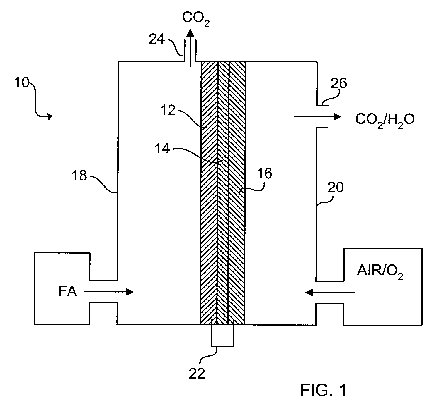
[0034]The schematic of FIG. 1 shows an exemplary direct organic fuel cell of the invention generally at 10. The fuel cell 10 includes an anode 12, a solid polymer proton-conducting electrolyte 14, and a gas diffusion cathode 16. The anode 12 is enclosed in an anode enclosure 18, while the cathode 16 is enclosed in a cathode enclosure 20. When an electrical load (not shown) is connected between the anode 12 and cathode 16 via an electrical linkage 22, electro-oxidation of an organic fuel occurs at the anode 12 and electro-reduction of an oxidizer occurs at the cathode 16.

[0035]The occurrence of different reactions at the anode 12 and cathode 16 gives rise to a voltage difference between the two electrodes. Electrons generated by electro-oxidation at the anode 12 are conducted through the linkage 22 and are ultimately captured at the cathode 16. Hydrogen ions or protons generated at the anode 12 are transported across the membrane electrolyte 14 to the cathode 16. Thus, a flow of curr...


PUM

PropertyMeasurementUnit
voltageaaaaaaaaaa
voltageaaaaaaaaaa
thickaaaaaaaaaa

Abstract

A direct organic fuel cell includes a formic acid fuel solution having between about 10% and about 95% formic acid. The formic acid is oxidized at an anode. The anode may include a Pt / Pd catalyst that promotes the direct oxidation of the formic acid via a direct reaction path that does not include formation of a CO intermediate.

Description

PRIORITY CLAIM[0001]This application claims priority of U.S. Provisional Application Serial No. 60 / 369,992, filed Apr. 4, 2002.STATEMENT OF GOVERNMENT INTEREST[0002]This invention was made with Government assistance under Department of Energy Grant No. DEGF-02-99ER14993. The Government has certain rights in the invention.FIELD OF THE INVENTION[0003]The invention generally relates to fuel cells and catalysts for fuel cells.BACKGROUND OF THE INVENTION[0004]Fuel cells are electrochemical cells in which a free energy change resulting from a fuel oxidation reaction is converted into electrical energy. Applications for fuel cells include battery replacement, mini and microelectronics, car engines, power plants, and many others. One advantage of fuel cells is that they are substantially pollution-free.[0005]In hydrogen fuel cells, hydrogen gas is oxidized to form water, with a useful electrical current produced as a byproduct of the oxidation reaction. A solid polymer membrane electrolyte ...

Claims


Application Information

Patent Timeline
Patent Type & Authority Patents(United States)
IPC IPC(8): H01M8/10H01M4/90H01M4/92H01M4/86H01M4/88H01M4/96
CPCH01M4/8605H01M4/881H01M4/8846H01M4/8853H01M4/8896H01M4/96H01M8/0271H01M8/04208H01M8/1004H01M8/1009H01M4/92Y02E60/521Y02E60/50
Inventor MASEL, RICHARD I.RICE, CYNTHIA A.WASZCZUK, PIOTRWIECKOWSKI, ANDRZEJ
Owner THE BOARD OF TRUSTEES OF THE UNIV OF ILLINOIS
Learn More