
Soller slit using low density materials

a low density, material technology, applied in the field of xray metrology, can solve the problems of large divergence angle, difficult control of the divergence of the beam of xray radiation, loss of well over half of the incident x-ray radiation on the device, etc., to achieve low density, increase transmission throughput efficiency, and low divergence

Inactive Publication Date: 2006-10-24
BRUKER TECH LTD
View PDF21 Cites 10 Cited by
  • Summary
  • Abstract
  • Description
  • Claims
  • Application Information

AI Technical Summary

Benefits of technology

This approach results in a significant increase in transmission efficiency to at least 60% and a reduction in divergence angles, enhancing the precision and effectiveness of X-ray collimation in diffractometry applications.

Problems solved by technology

Because of the nature of this type of radiation, it is often difficult to control its divergence.
One problem generally associated with Soller slit devices used for commercial applications such as X-ray diffractometry, however, is that they generally have relatively low transmission efficiencies and large divergence angles.
Thus, well over half of the X-ray radiation incident upon the device is lost and unusable for measurements in the application in which the Soller slit is being employed.
This typical divergence angle is large, and negatively impacts the Soller slit's ability to effectively collimate x-ray radiation for commercial applications such as X-ray diffractometry.
Although these metal sheets can be made extremely thin, the mechanical stability of such thin sheets is not sufficient for high precision X-ray applications.
For example, any curling or rumpling of the sheets, which is common with metals, will result in poor transmission through the Soller slit device, and consequently unpredictable divergence.
These metal foil devices yield relatively low transmission efficiencies.
Moreover, the transmission efficiencies of such devices diminishes as the required divergence is reduced (i.e., the quality of such devices' outputs becomes worse as their design constraints are made more restrictive).
The production of the Soller slit described therein requires expensive ceramic materials processing, and is therefore less desirable for commercial applications.

Method used


Image

  • Soller slit using low density materials
  • Soller slit using low density materials
  • Soller slit using low density materials

Examples


Embodiment Construction

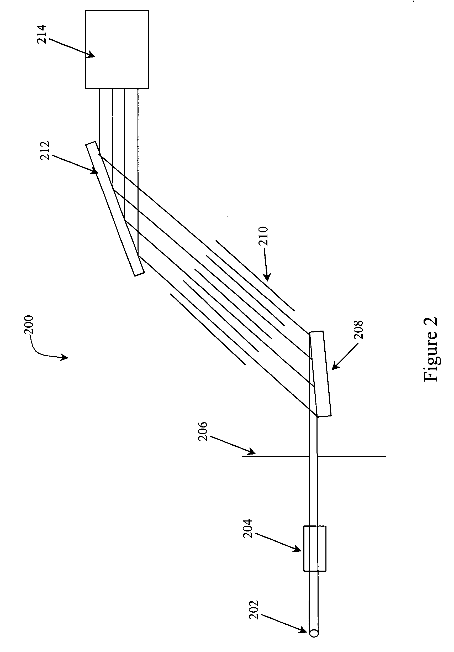
[0021]To facilitate an understanding of the principles that underlie the present invention, it will be described hereinafter with particular reference to embodiments thereof, and specific applications wherein it is used. It will be appreciated, however, that the practical applications of the invention are not limited to the particular embodiments described herein. Rather, the invention will find utility in a variety of different applications wherein a Soller slit X-ray collimator having a high transmission throughput efficiency and / or a low divergence is desirable. The present invention provides commercial advantages for multiple applications, as the Soller slit device of the present invention provides a greater transmission efficiency and a lower divergence angle than those associated with traditional optics used in high energy radiation applications, such as X-ray diffractometry.

[0022]FIG. 1 illustrates a Soller slit device 100. The Soller slit device is made up of multiple parall...


PUM

PropertyMeasurementUnit
thicknessaaaaaaaaaa
lengthaaaaaaaaaa
blade lengthaaaaaaaaaa

Abstract

A Soller slit device is provided for collimation of high energy radiation, such as X-ray or EUV radiation, and has a low angle of divergence (less than 0.1°) and a high transmission efficiency (60 to 80% or greater). The Soller slit is made up of multiple, parallel blades of low-density material, such as glass, mica, or the like, which can be treated to reduce reflectivity. The Soller slit device of the invention advantageously provides an increased peak intensity and decreased peak width in diffraction patterns produced in high energy diffractometry applications, such as X-ray diffractometry.

Description

[0001]This disclosure claims priority under 35 U.S.C. § 119(e) to U.S. Provisional Application No. 60 / 398,584 entitled Soller Slit Using Low Density Materials, filed on Jul. 26, 2002, the entire content of which is hereby incorporated by reference.FIELD OF THE INVENTION[0002]The present invention relates to X-ray metrology. Specifically, the invention relates to a device for controlling the divergence of a beam of X-rays.BACKGROUND OF THE INVENTION[0003]Various technologies make use of high energy radiation, such as X-ray and extreme ultraviolet (EUV) radiation. Because of the nature of this type of radiation, it is often difficult to control its divergence. One common optical element that is used to control the divergence of an X-ray beam is a collimator commonly called a Soller slit. Soller slits generally comprise an array of parallel, or nearly parallel, plates or blades that limit the divergence of an X-ray beam by simple blocking or absorption of divergent rays, which restrict...

Claims


Application Information

Patent Timeline
Patent Type & Authority Patents(United States)
IPC IPC(8): G21K1/02G01N23/20
CPCG21K1/025
Inventor BOWEN, DAVID KEITHPINA, LADISLAVINNEMAN, ADOLFMENZER, STEPHAN
Owner BRUKER TECH LTD
Learn More