Eureka AIR delivers breakthrough ideas for toughest innovation challenges, trusted by R&D personnel around the world.

Apparatus and method for immediate non-sequential state transition in a PN code generator

a pn code generator and non-sequential state technology, applied in the field of communication, can solve the problems of limited bandwidth available, reduce the complexity of computation, reduce the multiplication of vectors, and reduce the calculation time to achieve offset states.

Inactive Publication Date: 2006-10-17
NEC AMERICA
View PDF11 Cites 17 Cited by
  • Summary
  • Abstract
  • Description
  • Claims
  • Application Information

AI Technical Summary

Benefits of technology

[0012]It is still another object of the present invention to use a limited number of clock cycles of the PN generator to achieve a non-sequential PN generator state transition or jump. Further, the future LSSR state generation process used to accomplish a non-sequential state transition or jump can typically occur in a single clock cycle. As a result, no system level clocking delay is introduced to accomplish such a state transition or jump. Because there are a finite number of state transition or jumps that are possible before achieving received signal correlation or synchronization, that correlation can be achieved faster or significantly faster than by using existing methodologies.
[0014]It is still another object of this invention to reduce the multiplication of vectors in the PN code sequence generating process by inserting zero valued vectors or multiplication products or their equivalents to establish the desired remainder coefficients or function.

Problems solved by technology

Such signal bandwidth compression and decompression is useful because of limited availability of transmission signals over finite frequency bands.
Likewise, there are a limited number of bandwidths which are available for cellular telephone communications.

Method used


Image

  • Apparatus and method for immediate non-sequential state transition in a PN code generator
  • Apparatus and method for immediate non-sequential state transition in a PN code generator
  • Apparatus and method for immediate non-sequential state transition in a PN code generator

Examples


Embodiment Construction

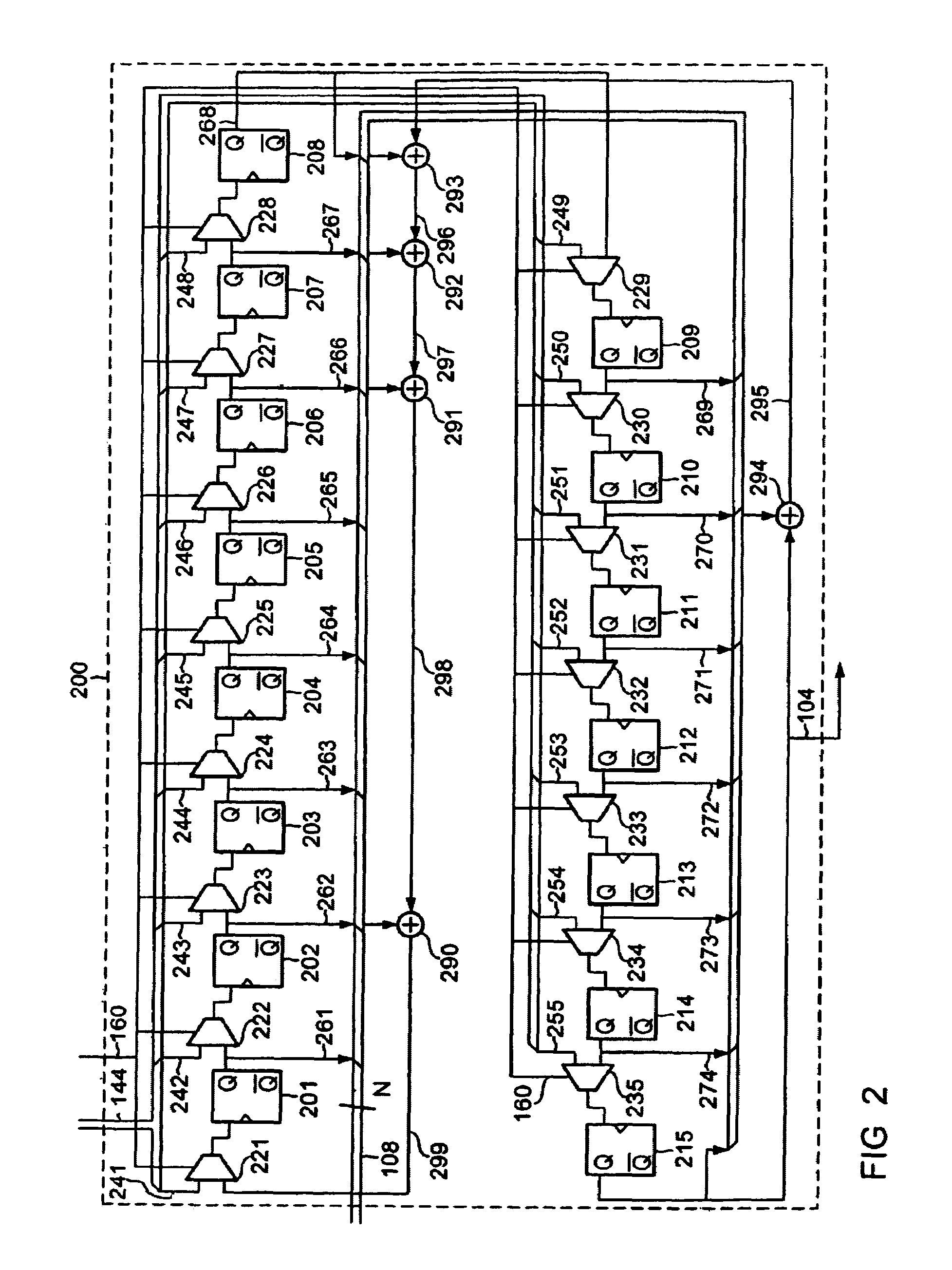
[0027]Referring generally to FIG. 1, it shows an overall block diagram of a circuit that implements the inventive concepts of this invention. Shown in FIG. 1 are major components of a preferred first embodiment of this invention's PN generation system, including, an N-Stage LSSR 200, Absolute Address bus 164, Computational Logic Circuit 500, a Decimal Counter 124, an N-bit wide LSSR State output bus 108, and a PN output signal 104. Control logic is used which is comprised of an Address Comparator 140, a State Comparator 192, a Hold-State D-type Flip-Flop 172, and logic function gates, specifically AND-gate 176, and OR-gate 196. Also used is Master Clock signal 154. Optionally, Direct State Load Bus 138 can be used as a multiplication input for vector data or other data, depending upon the configuration implemented. LSSR loading control signals New State signal 152 and Load Enable signal 160 are used to enable loading and also to synchronize loading (when necessary) into N-Stage LSSR...


PUM


Abstract

A power of a square matrix is determined in a time approximately proportional to the upper integer of the base-2 logarithm of the order of the matrix. A preferred embodiment uses two types of look-up tables and two multipliers for a matrix of 15×15, and is applied to a pseudorandom noise (PN) sequence phase correlation or state jumping circuit. An exact state of a PN code can be determined or calculated from applying an appropriate offset value into a control circuit. The control circuit can produce a PN sequence state from the offset value and typically does so within one system clock period regardless of the amount of the offset. Once the exact state is determined, it is loaded into a state generator or linear sequence shift register (LSSR) for generating a subsequent stream of bits or symbols of the PN code. The PN generator system may include state computing logic, a maximum length PN generator, a zero insertion circuit and a zero insertion skipping circuit.

Description

FIELD OF THE INVENTION[0001]The present invention generally relates to the field of communications, and more specifically to cellular telephones, historically referred to as radiotelephones. Particularly, the invention relates to a pseudorandom noise (PN) sequence generator for generating a PN code sequence capable of being used in applications such as those which use direct sequence spreading of the spectrum (DSSS) in the communication signals used by a digital communication system.BACKGROUND OF THE INVENTION[0002]In DSSS communication systems, PN generators are commonly used to spread or despread the information within the transmitted signal since the information signal bandwidth is much narrower than the spread signal. Such signal bandwidth compression and decompression is useful because of limited availability of transmission signals over finite frequency bands. However, the demand for information and the ability to transmit that information is increasing due to the expanding pr...

Claims


Application Information

Patent Timeline
Patent Type & Authority Patents(United States)
IPC IPC(8): G06F7/58G06F1/02H04J11/00H04J13/00
CPCG06F7/584G06F2207/582H04J13/0022H04J13/10
Inventor YANG, GANGZHANG, NING
Owner NEC AMERICA
Why Eureka
Eureka Blog
Learn More