Low temperature LED lighting system

a technology of led lighting and low temperature, which is applied in the field of low temperature led lighting systems, can solve the problems of inefficient colder temperature, difficult fire, and inability to start flourescent tubes in sub-zero temperatures, and achieves the effects of low cost, low energy consumption, and low cos

Inactive Publication Date: 2006-10-17
THE ARTAK TER HOVHANISSIAN PATENT TRUST
View PDF21 Cites 144 Cited by
  • Summary
  • Abstract
  • Description
  • Claims
  • Application Information

AI Technical Summary

Benefits of technology

[0013]The present invention resides in a lighting system used in lower temperature environments, such as refrigeration or freezer units and the like. The present invention generally comprises a plurality of light emitting diodes attached to a support member mounted within a refrigeration unit for illuminating the contents thereof. Light emitting diodes (LED's) are electronic components which do not have a filament like

Problems solved by technology

However, use of flourescent lights has many drawbacks.
It is difficult to fire and continue to keep flourescent tubes lit in low temperature environment applications as the mixture of gas must reach and maintain a certain elevated temperature to fire and remain lit.
In fact, flourescent tubes cannot be started in sub-zero temperatures and are very inefficient in colder temperatures above zero.
Higher frequencies have been applied to the flourescent tubes to cause the gas mixture to continually generate light, however the high frequency causes electromagnetic interference (EMI) which is costly to filter.
Unfiltered EMI caused by the generated high frequencies can cause nearby electronic devices to malfunction or even fail.
The flourescent tube filaments are easily broken by vibration and from extreme variations from hot to cold, resulting in a shorter operational life span of the flourescent tubes.
Flourescent tubes present additional problems when used in cold environment applications.
The filaments of the flourescent tubes are easily burnt or broken, and the thin-walled glass used in the flourescent tubes is susceptible to breakage.
Such maintenance increases the cost of operating the refrigeration units.
Such approval can be time consuming and

Method used


Image

  • Low temperature LED lighting system
  • Low temperature LED lighting system
  • Low temperature LED lighting system

Examples


Embodiment Construction

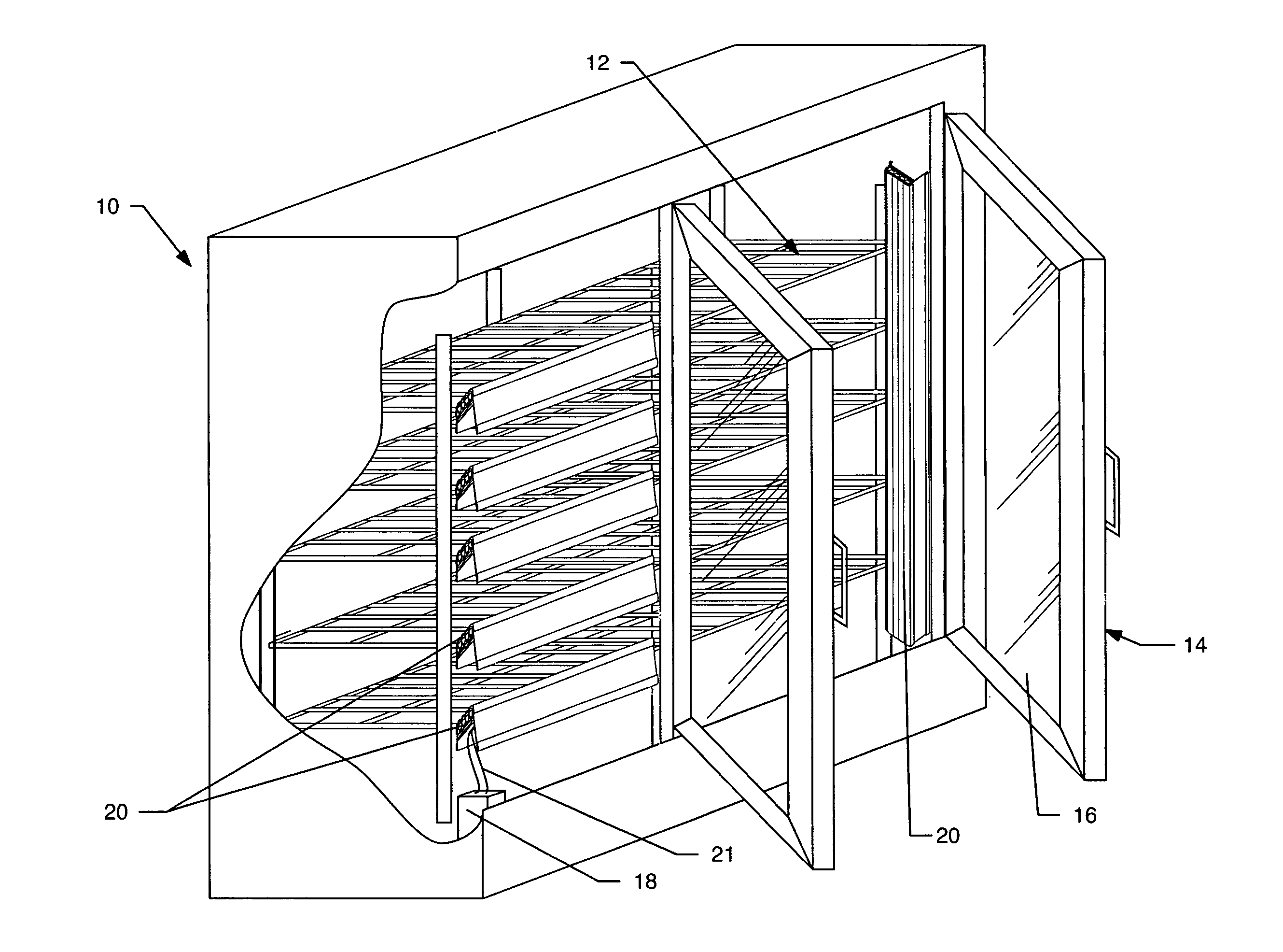
[0032]As shown in the drawings for purposes of illustration, the present invention is concerned with a lighting system used in low temperature applications, such as refrigeration units, freezer units the like.

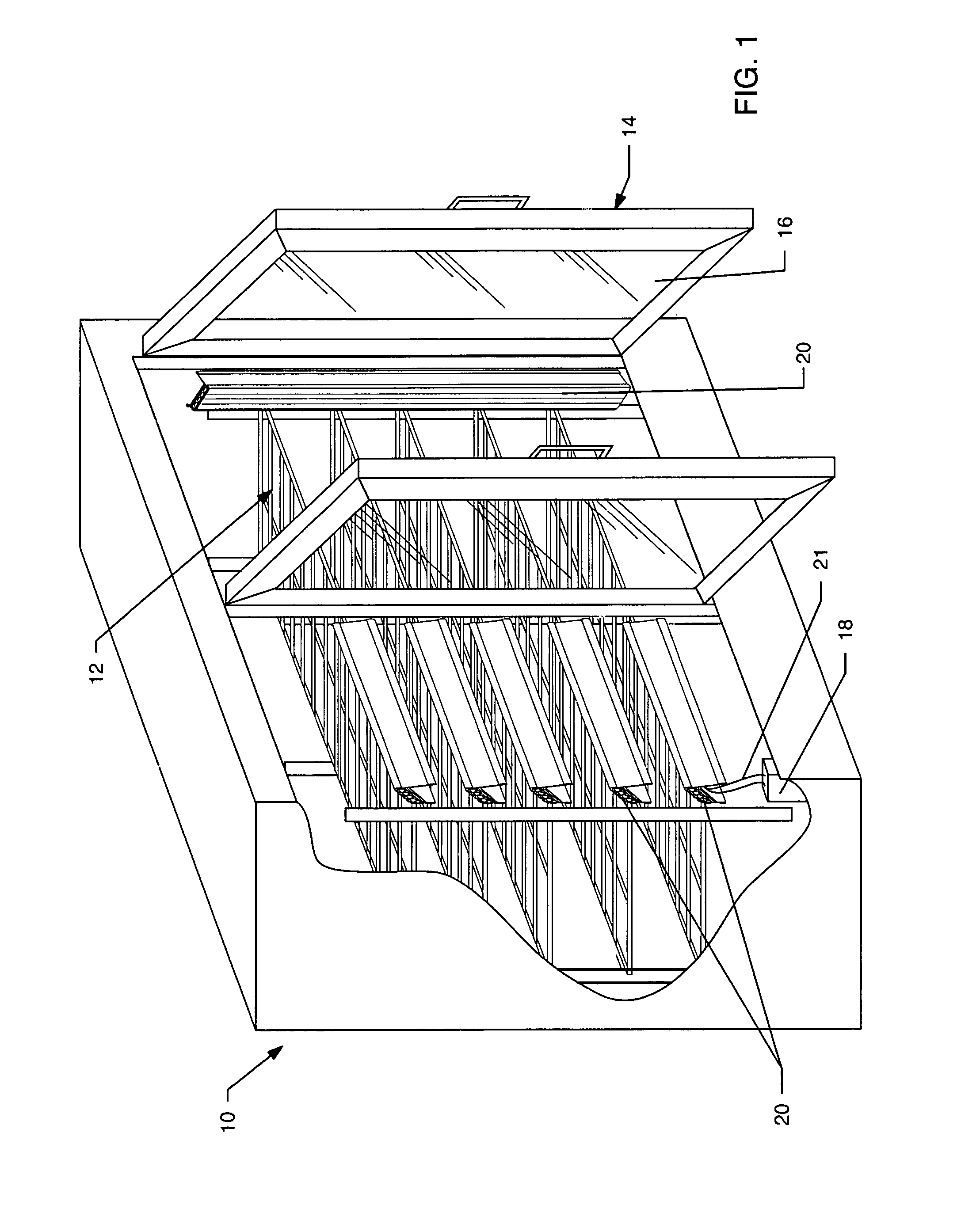
[0033]With reference now to FIG. 1, an exemplary refrigeration unit 10 is illustrated which is commonly used in supermarkets and the like. Although such a refrigeration unit 10 is illustrated for exemplary purposes, it should be understood by those skilled in art that the present invention can be utilized in any number of different low temperature applications in different settings. However, the present invention is particularly adapted for use in such refrigeration units 10. Such refrigeration units 10 include a plurality of shelves 12 in an interior cavity thereof for storing refrigerated or frozen product. Doors 14 are provided at the front of the refrigeration unit 10 to allow access to the product. Typically, the doors 14 include glass or clear panes 16 to enable viewing o...


PUM


Abstract

A lighting system for low temperature environments includes a plurality of light emitting diodes attached to a support member mounted within a refrigeration unit or the like for illuminating contents thereof. A reflector is disclosed adjacent to the light emitting diodes for dispersing the light therefrom. A light transmitting cover overlies the light emitting diodes, and preferably includes non-planar surfaces for dispersing light onto objects within the refrigeration unit. A power supply converts alternating current voltage to a lower direct current voltage for powering the light emitting diodes in a safe manner.

Description

RELATED APPLICATION[0001]This application claims priority from U.S. Provisional Application Ser. No. 60 / 347,617, filed Jan. 10, 2002.BACKGROUND OF THE INVENTION[0002]This invention relates to lighting systems. More particularly, the present invention relates to a light emitting diode lighting system which operates in a reduced temperature environment, such as in a refrigerator or freezer unit.[0003]In the grocery store, frozen foods such as juices, ice cream and vegetables, as well as those which need to be maintained at lowered temperatures such as diary products and fresh meat, must be stored in refrigeration units. The refrigeration units which contain these products must be properly lit as the associated shelving and doors create shadows or otherwise block outside ambient light from entering the refrigeration unit.[0004]Flourescent lights have been used in such applications because the flourescent tubes are brighter and generate less heat than incandescent bulbs. However, use of...

Claims


Application Information

Patent Timeline
IPC IPC(8): F21V33/00F25D23/00A47F3/00A47F3/04F21S2/00F25D27/00
CPCA47F3/001A47F3/0404F25D27/00F21S2/005F21S4/003F21W2131/305F21W2131/405F21Y2101/02F21S4/20F21Y2115/10
Inventor TER-HOVHANNISIAN, ARTAK
Owner THE ARTAK TER HOVHANISSIAN PATENT TRUST
Why Eureka
Try Eureka