
Radio transmitting/receiving apparatus and intermittent transmission/reception control method of radio transmitting/receiving apparatus

a radio transmitting/receiving apparatus and radio transmission technology, applied in power management, high-level techniques, sustainable buildings, etc., can solve the problems of increasing the average power consumption, wasting reception power, and wasting reception power, so as to minimize the time taken to transmit, the effect of wasting no reception power and little power

Inactive Publication Date: 2006-08-31
NEC CORP
View PDF4 Cites 40 Cited by
  • Summary
  • Abstract
  • Description
  • Claims
  • Application Information

AI Technical Summary

Benefits of technology

The present invention relates to a radio transmitter / receiver and an intermittent transmission / reception control method to reduce battery power consumption. The technical effect of the invention is to prolong battery life by minimizing standby power consumption on standby for reception by intermittently transmitting and receiving signals. However, the conventional method had drawbacks such as wasting power consumption due to long stabilization time for the oscillator circuit, frequent detection of unwanted signals, and inability to recognize ID until a preamble of 8*N bits or more is detected. The invention proposes a new method to overcome these drawbacks and achieve better results.

Problems solved by technology

Consequently, the radio transmitter / receiver cannot shorten the time necessary for intermittent reception, and wastes the reception power.
Therefore, the radio transmitter / receiver reacts to unwanted signals, and frequently performs ID check, which often causes an increase in average power consumption.
Consequently, when the activation of others frequently occurs, the radio transmitter / receiver consumes power wastefully, resulting in an increase in average power consumption.

Method used


Image

  • Radio transmitting/receiving apparatus and intermittent transmission/reception control method of radio transmitting/receiving apparatus
  • Radio transmitting/receiving apparatus and intermittent transmission/reception control method of radio transmitting/receiving apparatus
  • Radio transmitting/receiving apparatus and intermittent transmission/reception control method of radio transmitting/receiving apparatus

Examples


Embodiment Construction

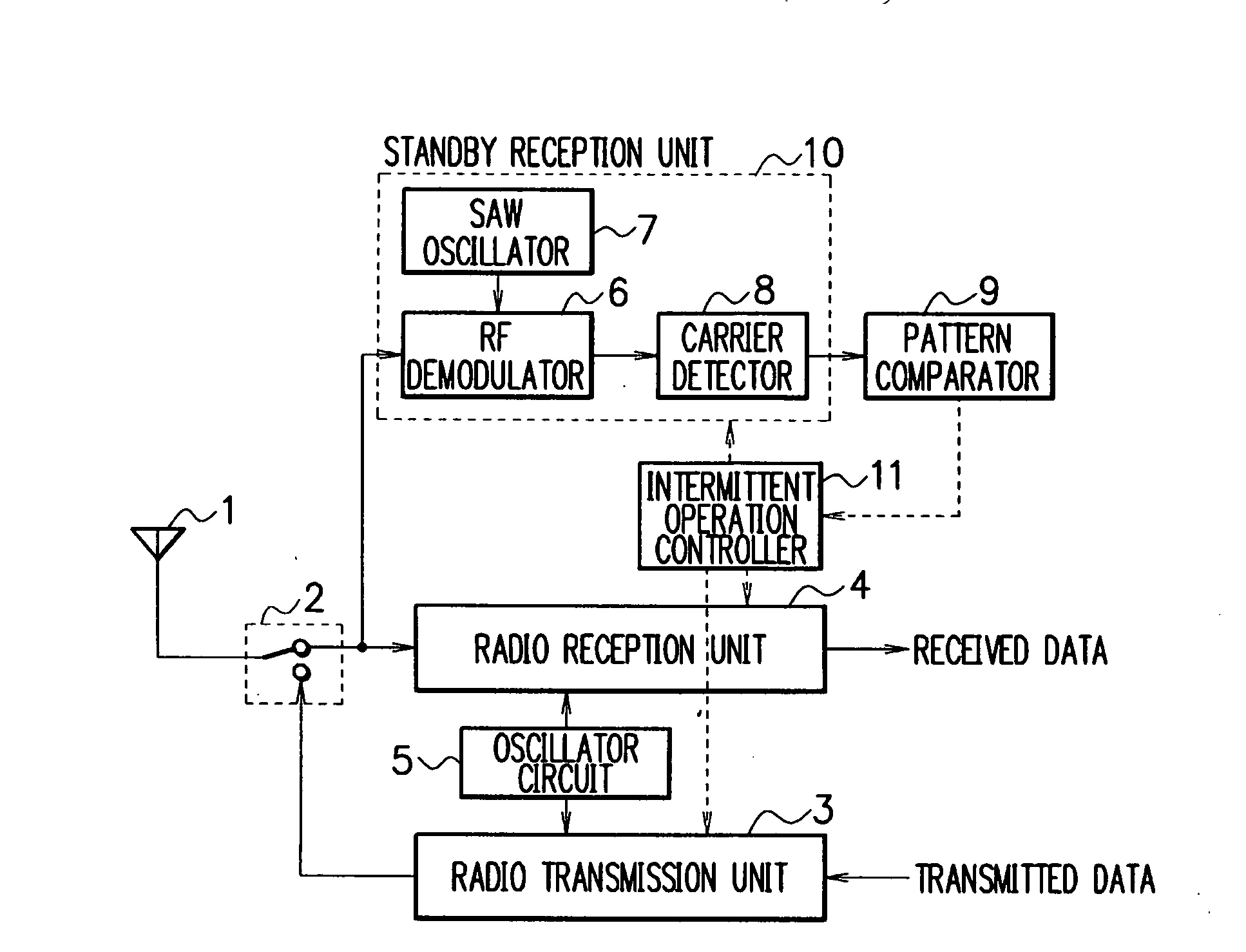
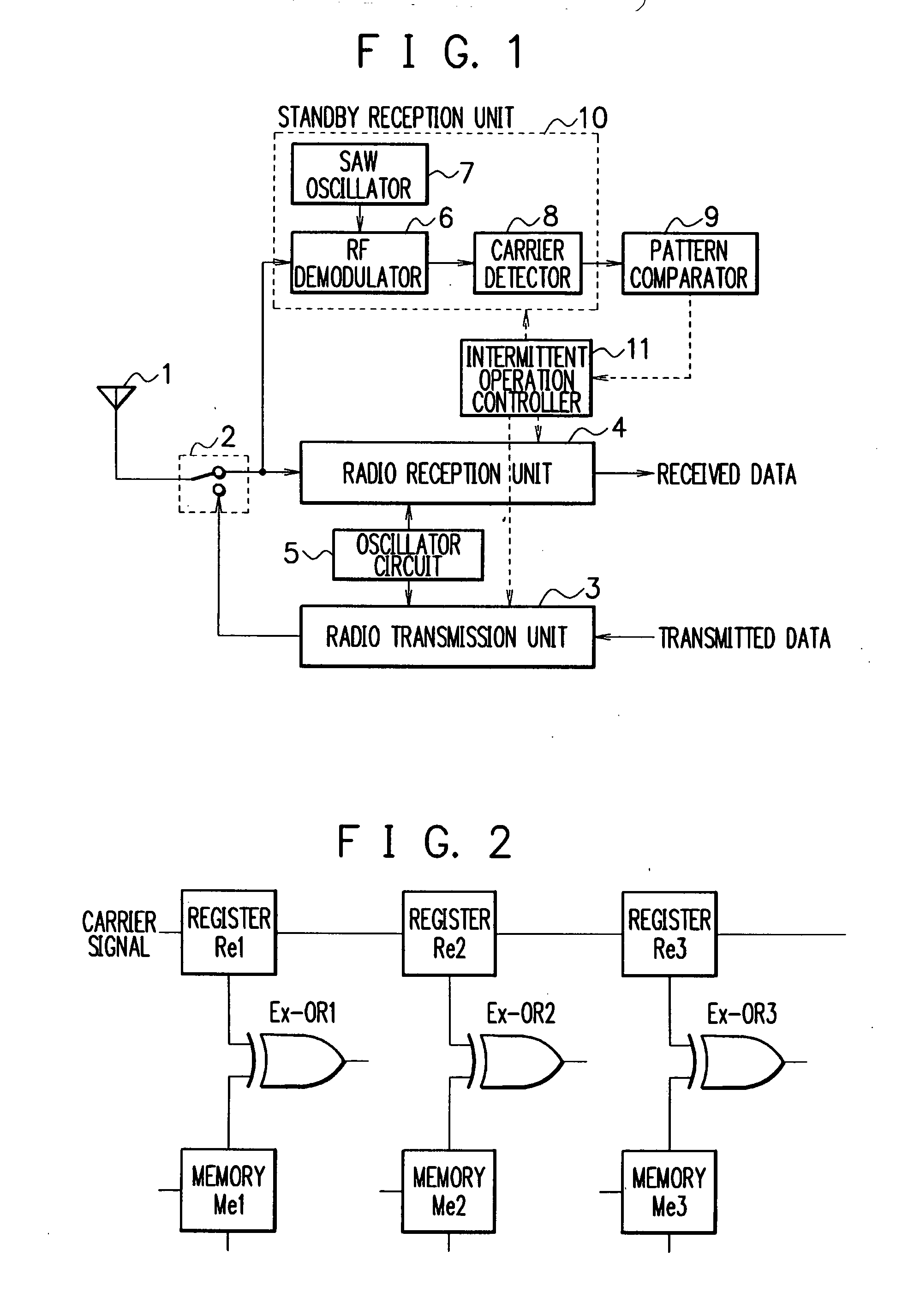
[0048]FIG. 1 is a block diagram showing a radio transmitter / receiver to which is applied an intermittent transmission / reception control method for a radio transmitter / receiver according to an embodiment of the present invention.

[0049] The radio transmitter / receiver mainly comprises an antenna 1, a transmission / reception changeover switch 2, a radio transmission unit 3, a radio reception unit 4, and an oscillator circuit 5. The radio transmitter / receiver further comprises, in addition to the radio reception unit 4, a standby reception unit 10 including an RF (Radio Frequency) demodulator 6, a SAW oscillator 7, and a carrier detector 8. The radio transmitter / receiver yet further comprises a pattern comparator 9 for comparing the pattern of presence and absence of the carriers with a predetermined pattern, and an intermittent operation controller 11 for controlling the intermittent operation of the respective radio transmission unit 3, radio reception unit 4, oscillator circuit 5 and ...


PUM


Abstract

A radio transmitter / receiver and an intermittent transmission / reception control method thereof, capable of reducing the reception startup time as well as suppressing reception power consumption. A radio transmitter / receiver used for ad hoc communication is provided with a dedicated standby reception unit (10) having a simple combination of an RF demodulator (6) and a SAW oscillator (7) only to detect a carrier. For a time period of several bits, the activation system of the radio transmitter / receiver intermittently receives activation selection signals transmitted using ASK (or OOK) modulation prior to a preamble signal, and makes an activation selection based on the pattern of presence and absence of the carriers of the signals. As a result, the reception startup time can be shortened, and less reception power is required.

Description

TECHNICAL FIELD [0001] The present invention relates to a radio transmitter / receiver, and an intermittent transmission / reception control method thereof. BACKGROUND ART [0002] In the case of collecting data (every type of sensing data including environmental data such as temperature, humidity, acceleration and CO2 concentration, image data such as an image of a river in flood, location information data, etc.) with battery-powered wireless sensor modules or the like through ad hoc communication, the battery survival time needs to be prolonged by minimizing standby power consumption to reduce average power consumption. [0003] There has been an intermittent transmission / reception control system in which a preamble is detected in signals from other transmitters, well-known as a method of reducing power consumption on standby for reception. [0004]FIG. 17 is a block diagram showing a radio transmitter / receiver to which is applied a conventional intermittent transmission / reception control m...

Claims


Application Information

Patent Timeline
Patent Type & Authority Applications(United States)
IPC IPC(8): H04B1/16H04B1/38
CPCH04W52/0235H04W88/02Y02B60/50Y02D30/70
Inventor HOKIMOTO, TAKEHIROKAWASAKI, DAISUKEARAI, MASANOBUKOJIMA, KANAME
Owner NEC CORP
Learn More