
Method and system for DNA recognition biometrics on a fob

a biometric and transponder reader technology, applied in the direction of program control, testing/monitoring control system, instruments, etc., can solve the problems of initiation and completion of unwanted transactions, undue overhead, limited conventional fobs, etc., and achieve the effect of facilitating the completion of transactions

Inactive Publication Date: 2006-10-17
LIBERTY PEAK VENTURES LLC
View PDF434 Cites 99 Cited by
  • Summary
  • Abstract
  • Description
  • Claims
  • Application Information

AI Technical Summary

Benefits of technology

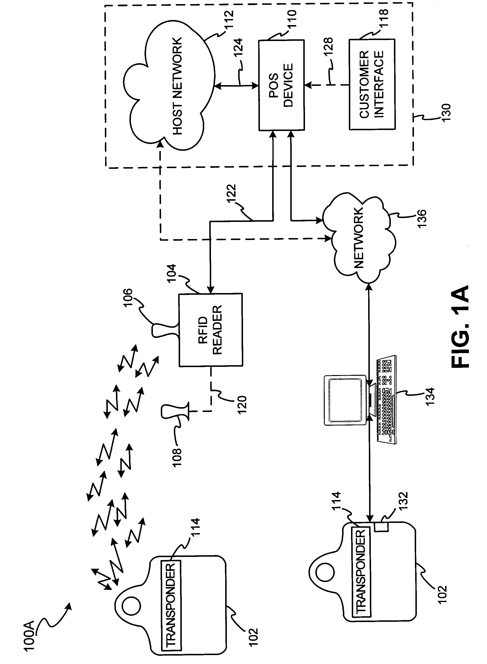
"The patent describes a system and method for using RFID technology to initiate and complete financial transactions. The system includes an RFID reader and a fob, which can be placed in proximity to the reader for interrogation. The fob includes a RFID transponder for receiving RFID signals and providing transponder system account data. The fob can be in the form of a fob, tag, card, or other form factor like a wristwatch or cell phone. The system also includes a point of interaction device for completing the transaction, such as a computer interface or a merchant interface. The system distinguishes between the usage of a fob and a charge or credit card sharing the same funding source as the fob. The fob user can also manage the associated account information and update it in real-time or at the time the account provider receives the updated information. The system can also approve the transaction request and provide authorization to the merchant. The technical effects of the patent include improved security, convenience, and efficiency in using RFID technology for financial transactions."

Problems solved by technology

Inadvertent presentation of the fob may result in initiation and completion of an unwanted transaction.
In this way, the conventional transaction processing method involves an indirect path which causes undue overhead due to the use of the third-party server.
In addition, conventional fobs are limited in that they must be used in proximity to the Point of Sale device.
More particularly, conventional fobs are not effective for use in situations where the user wishes to conduct a transaction at a point of interaction such as a computer interface.
Existing transponder-reader payment systems are also limited in that the conventional fob used in the systems is only responsive to one interrogation signal.
Thus, if the RFID reader of the system provides only an interrogation signal to which the fob is incompatible, the fob will not be properly activated.
Existing transponder-reader payment systems are additionally limited in that the payment systems are typically linked to a funding source associated with the transponder which includes a predetermined spending limit.
Thus no flexibility is provided in instances where the payment is requested which exceeds the predetermined spending limit.
Further, traditional transponder-reader systems do not permit the user to manage the system user account data.
This is extremely problematic where the user wishes to change a transponder-reader system funding source to a source which provides more available spending room, or where changes are made to the user's status (e.g., change in address, phone number, email, etc.) for which the transponder-reader account provider wishes to readily update the user's account.
Further still, existing transponder-reader systems do not usually permit means for automatically incenting the use of the fob associated with the system as opposed to the credit or charge card associated with the fob.
That is, conventional transponder-reader systems do not provide a means for encouraging usage of the transponder reader system by encouraging use of the fob product since the present systems do not sufficiently distinguish between usage of a system transponder and a charge or credit card account associated with the transponder.
Still further, present systems are limited in that the systems are unable to track credit or charge card usage and fob usage for a single funding source.
Thus, a fob user is unable to adequately chart, analyze or compare fob usage to the usage of the associated card.
This is especially problematic where the funding source is used by more than one entity (e.g., spouses, multiple company personnel, etc.) or where one entity may use the fob and a separate entity may use the card associated with the fob.

Method used


Image

  • Method and system for DNA recognition biometrics on a fob
  • Method and system for DNA recognition biometrics on a fob
  • Method and system for DNA recognition biometrics on a fob

Examples


Embodiment Construction

[0049]The present invention may be described herein in terms of functional block components, screen shots, optional selections and various processing steps. Such functional blocks may be realized by any number of hardware and / or software components configured to perform to specified functions. For example, the present invention may employ various integrated circuit components, (e.g., memory elements, processing elements, logic elements, look-up tables, and the like), which may carry out a variety of functions under the control of one or more microprocessors or other control devices. Similarly, the software elements of the present invention may be implemented with any programming or scripting language such as C, C++, Java, COBOL, assembler, PERL, extensible markup language (XML), JavaCard and MULTOS with the various algorithms being implemented with any combination of data structures, objects, processes, routines or other programming elements. Further, it should be noted that the pre...


PUM


Abstract

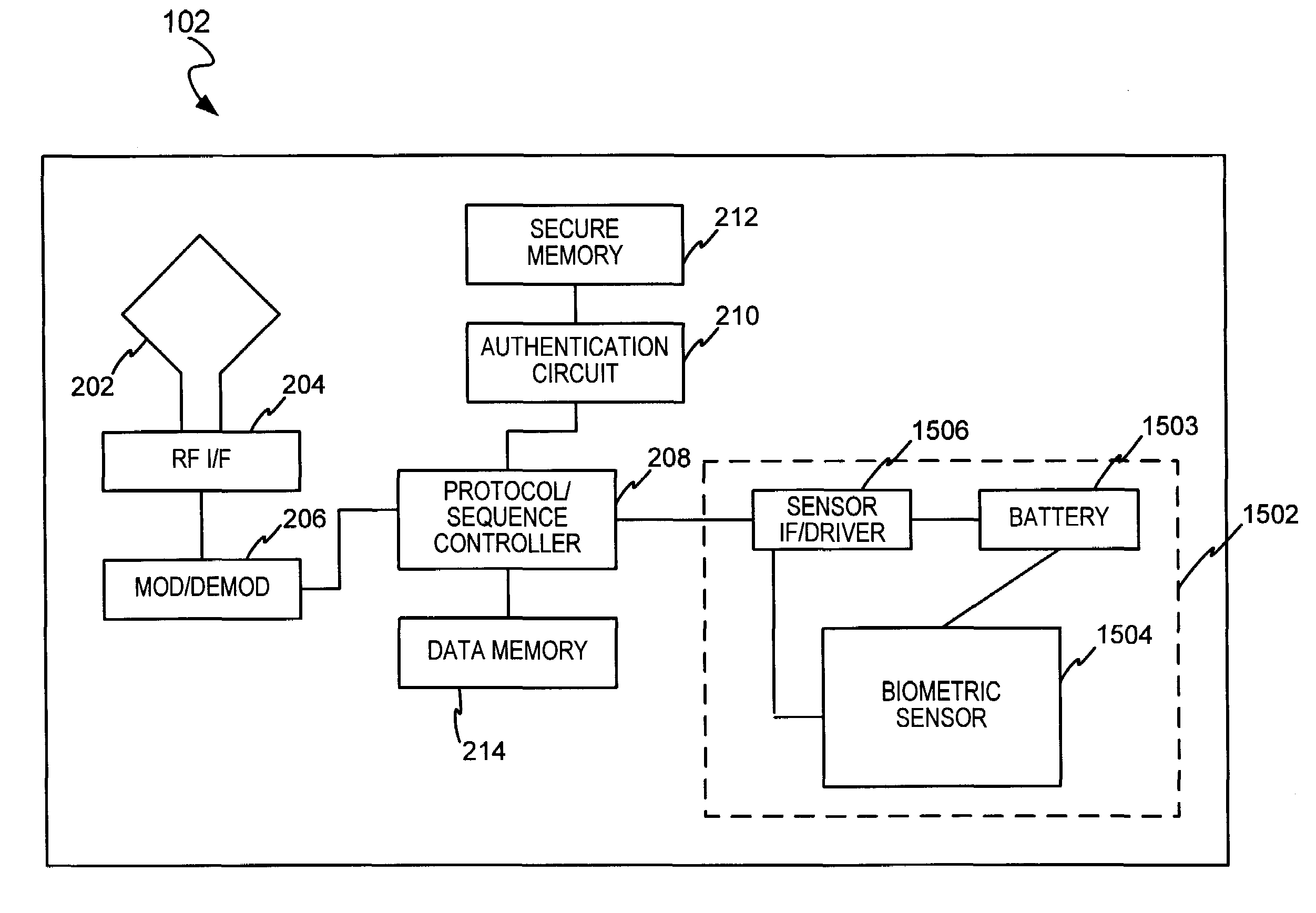
The present invention discloses a system and methods for biometric security using DNA recognition biometrics in a transponder-reader system. The biometric security system also includes a DNA scan sensor that detects biometric samples and a device for verifying biometric samples. In one embodiment, the biometric security system includes a transponder configured with a DNA scan sensor. In another embodiment, the system includes a reader configured with a DNA scan sensor. In yet another embodiment, the present invention discloses methods for proffering and processing DNA scan samples to facilitate authorization of transactions.

Description

CROSS REFERENCE TO RELATED APPLICATIONS[0001]This invention is a continuation in part of U.S. Ser. No. 10 / 340,352, filed on Jan. 10, 2003, and entitled “SYSTEM AND METHOD FOR INCENTING PAYMENT USING RADIO FREQUENCY IDENTIFICATION IN CONTACT AND CONTACTLESS TRANSACTIONS.” The '352 application itself claims priority to U.S. patent application Ser. No. 10 / 192,488, entitled “SYSTEM AND METHOD FOR PAYMENT USING RADIO FREQUENCY IDENTIFICATION IN CONTACT AND CONTACTLESS TRANSACTIONS,” filed on Jul. 9, 2002 (which itself claims priority to U.S. Provisional No. 60 / 304,216, filed on Jul. 10, 2001); U.S. patent application Ser. No. 10 / 318,432, entitled “SYSTEM AND METHOD FOR SELECTING LOAD OPTIONS FOR USE IN RADIO FREQUENCY IDENTIFICATION IN CONTACT AND CONTACTLESS TRANSACTIONS,” filed Dec. 13, 2002; U.S. patent application Ser. No. 10 / 318,480, entitled “SYSTEM AND METHOD FOR PAYMENT USING RADIO FREQUENCY IDENTIFICATION IN CONTACT AND CONTACTLESS TRANSACTIONS,” filed Dec. 13, 2002; and, U.S. P...

Claims


Application Information

Patent Timeline
Patent Type & Authority Patents(United States)
IPC IPC(8): G06K19/00G06Q20/00G07C9/00
CPCG06Q20/00G06Q20/04G06Q20/14G06Q20/28G06Q20/32G06Q20/327G06Q20/3278G06Q20/342G06Q20/40G06Q20/40145G07C9/00111G07C9/00119G07F7/025H04L9/3231H04L2209/805H04L2209/56G07C9/29G07C9/28G06Q20/321
Inventor BEENAU, BLAYN W.BONALLE, DAVID S.FIELDS, SETH W.GRAY, WILLIAM J.LARKIN, CARLMONTGOMERY, JOSHUA L.SAUNDERS, PETER D.
Owner LIBERTY PEAK VENTURES LLC
Learn More