Ion detector for ion beam applications

a technology of ion beam and detector, applied in the direction of instruments, heat measurement, material analysis using wave/particle radiation, etc., can solve the problems of damage due to electrostatic discharge, poor signal-to-noise ratio of ion mode, and one serious limitation of ion mode, so as to improve the net detected signal

Active Publication Date: 2006-10-10
GLOBALFOUNDRIES US INC
View PDF15 Cites 34 Cited by
  • Summary
  • Abstract
  • Description
  • Claims
  • Application Information

AI Technical Summary

Benefits of technology

[0018]Another feature of the invention is that electrons emitted from the multiplier electrode are collected by a detector, thereby increasing the amount of the detected signal.

Problems solved by technology

The buildup of positive charge at various locations within the workpiece can result in damage due to electrostatic discharge (ESD).
One serious limitation of ion mode, however, is total signal intensity.
The number of secondary ions generated by the primary beam is significantly lower than the number of secondary electrons, so the signal-to-noise ratio of ion mode is poor compared to electron mode.
In particular, when the primary beam is small (below about 20 pA), the number of secondary ions is so low that ion mode becomes impractical.
Nevertheless, in the semiconductor industry there is growing concern over beam-induced charge damage.
All of these factors make modern ICs more susceptible to charge damage, so it is necessary to keep beam currents low and use charge neutralization during FIB processing.

Method used


Image

  • Ion detector for ion beam applications
  • Ion detector for ion beam applications
  • Ion detector for ion beam applications

Examples


Embodiment Construction

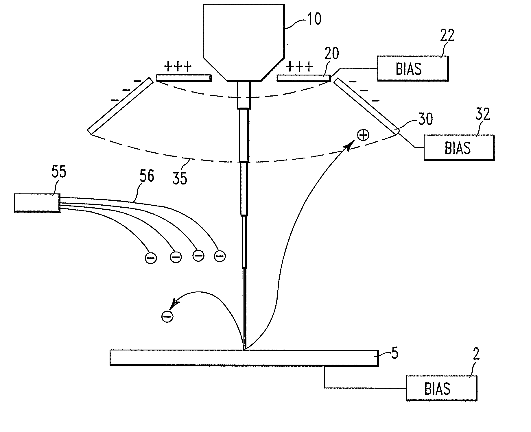
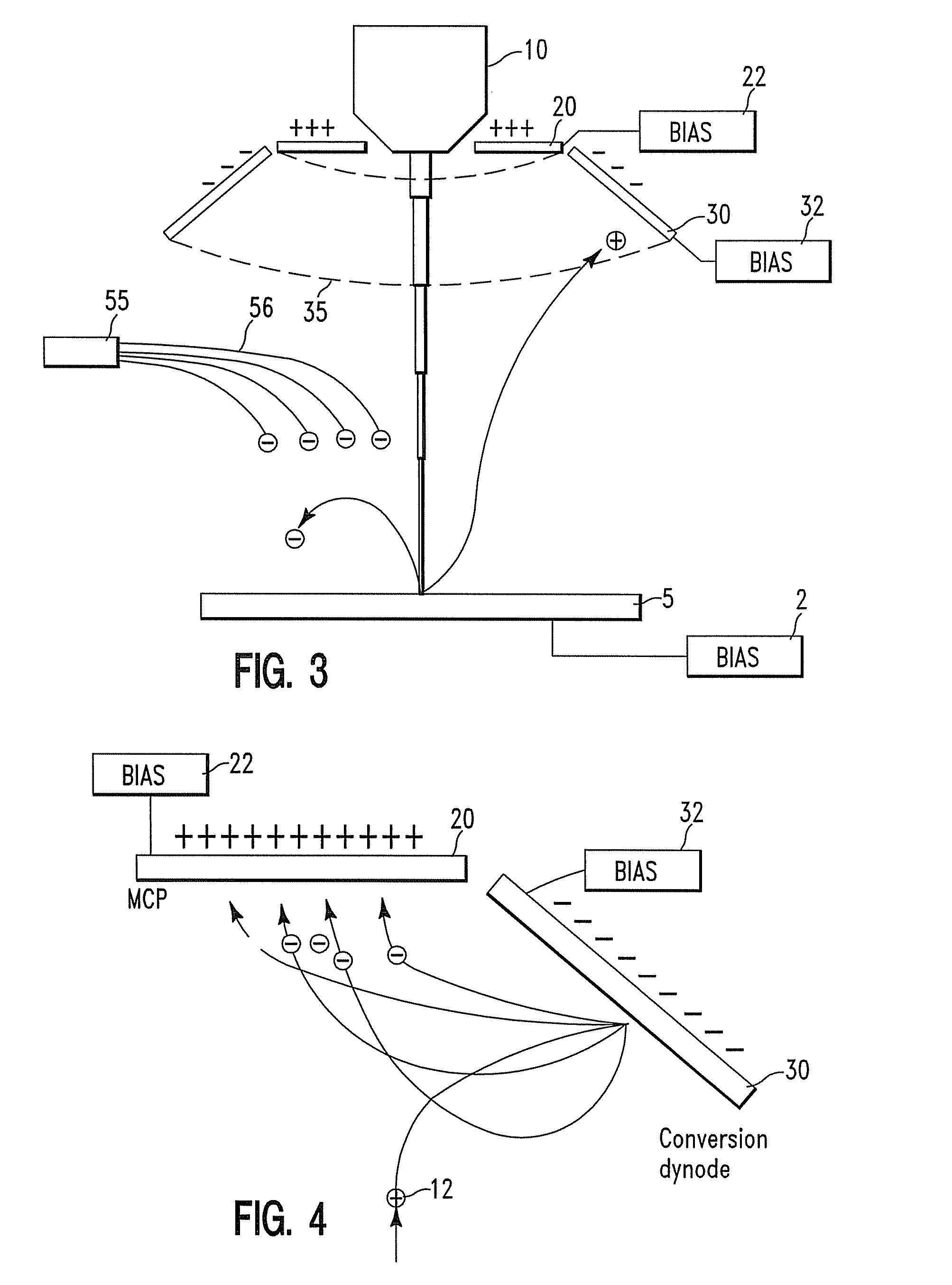
[0027]FIG. 3 illustrates in cross section a version of the invention that includes the addition of a conversion dynode 30 to the FIB detector hardware. The conversion dynode is preferably in the shape of a frustum of a cone (which may have a non-metallic coating) that extends azimuthally about the primary beam 50 and is located near the MCP. Dashed lines 35 indicate the path of the front portion of the dynode 30. In a conventional cross section, lines 35 would have gone straight across, but that would have blocked the MCP. Instead, for improved clarity in presentation, the front portion of the figure, in front of the plane of the cross section, is shown pictorially.

[0028]The material of the dynode has a low work function so that electrons are easily released. Commercially available photomultipliers use coatings on multiplier electrodes that are suitable.

[0029]FIG. 3 indicates the operation of the system in ion mode, with electron source 55 generating electrons to neutralize residual...


PUM

PropertyMeasurementUnit
shapeaaaaaaaaaa
electricalaaaaaaaaaa
electrical signalaaaaaaaaaa

Abstract

Detection of weak ion currents scattered from a sample by an ion beam is improved by the use of a multiplier system in which a conversion electrode converts incident ions to a number of secondary electrons multiplied by a multiplication factor, the secondary electrons being attracted to an electron detector by an appropriate bias. In one version, the detector is a two stage system, in which the secondary electrons strike a scintillator that emits photons that are detected in a photon detector such as a photomultiplier or a CCD.

Description

TECHNICAL FIELD[0001]The field of the invention is that of focused ion beam tools.BACKGROUND OF THE INVENTION[0002]Existing Technology and Problems Encountered[0003]Focused Ion Beam (FIB) tools produce a focused, energetic beam of positively charged ions (subsequently referred to as the primary ion beam or primary ions), which can be used to image or alter microscopic structures. When the primary ion beam is scanned over the surface of the sample, an assortment of secondary particles is sputtered from the surface: electrons, ions, and neutrals.[0004]In commercial FIB tools, a portion of the charged secondary particles is diverted to a detector, usually a microchannel plate (MCP) or scintillator-type detector, where the signal is amplified and measured. To create an image, the measured secondary signal intensity is converted to a grey-scale color and displayed on a screen.[0005]When an MCP detector is used, two imaging modes are generally available, depending on which secondary parti...

Claims


Application Information

Patent Timeline
Patent Type & Authority Patents(United States)
IPC IPC(8): G01N23/225H01J37/00
CPCH01J37/244H01J2237/2448H01J2237/3174
Inventor HERSCHBEIN, STEVEN B.RANA, NARENDERRUE, CHADSIEVERS, MICHAEL R.
Owner GLOBALFOUNDRIES US INC
Why Eureka
Try Eureka