
Method of manufacturing fabric with rubber for tire

a technology of rubber coating and tire, which is applied in the field of tire manufacturing method, can solve the problems of insufficient tensile force, inability to improve uniformity, and structure in which the weft “b” is cut after, and achieves the effect of high degree of uniformity

Inactive Publication Date: 2006-10-03
SUMITOMO RUBBER IND LTD
View PDF3 Cites 7 Cited by
  • Summary
  • Abstract
  • Description
  • Claims
  • Application Information

AI Technical Summary

Benefits of technology

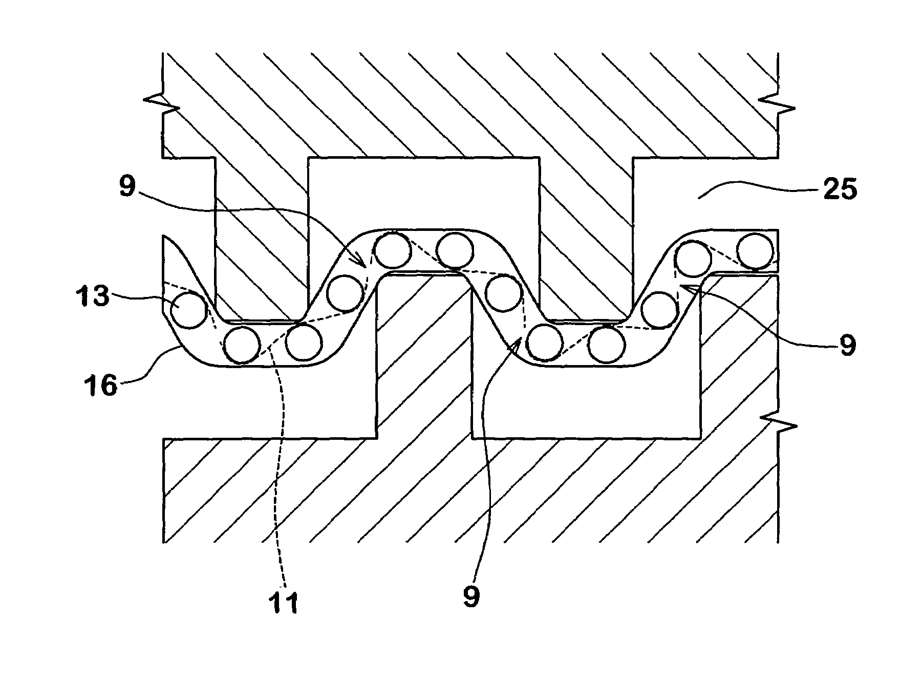
The present invention provides a method for manufacturing a rubber coated fabric for a tire that can achieve a high degree of uniformity without adversely affecting the outer appearance normally caused by passing the rubber coated fabric through rollers. This is achieved by cutting the weft of the fabric base substance at a cut pitch twice to five times an arrangement pitch of the warp, using a low ductility yarn and a cutting device comprising a pair of rollers with specific groove widths and insertion depths. The technical effect is a more uniform cut length of the weft without the need for irradiating with an electron beam.

Problems solved by technology

If the fabric “d”, coated with rubber, is passed through without irradiating with the electron beam, there is the case where the weft “b” is displaced and thus a sufficient tensile force cannot be applied, due to a soft topping rubber.
Therefore, a cut length is widely scattered such that a portion which is not partially cut is generated, and accordingly uniformity cannot be sufficiently improved.
However, the structure in which the weft “b” is cut after irradiating with the electron beam tends to become deteriorated in its outer appearance such that a concave-convex trace generated at a time of passing through the rollers remains on the surface of the fabric “d”, whereby a wavy undulation is generated on the side surface of the tire.

Method used


Image

  • Method of manufacturing fabric with rubber for tire
  • Method of manufacturing fabric with rubber for tire
  • Method of manufacturing fabric with rubber for tire

Examples


examples

[0058]A rubber coated fabric was formed on the basis of the specifications in Table 1, using the manufacturing method of the present invention. Further, the uniformity or the like of the tire cord arrangement at the time of expanding the carcass ply material in a troidal shape was evaluated by visual observation, after which the carcass ply material using the rubber fabric is cylindrically wound around a forming drum.

[0059]

TABLE 1ComparativeComparativeComparativeComparativeComparativeExample 1Example 1Example 2Example 2Example 2Example 3Example 4Example 5Example 4Material ofCottonCottonCottonCottonCottonCottonCottonCottonCottonweftCut ductility3815 23 15 15 15 15 15 (%)First rollerGroove444413666width W1(mm)Protruding35%35%35%35%35%35%35%15%35%width T1 / W2Insertion333333333depth h2(mm)Second rollerGroove444413666width W2(mm)Protruding35%35%35%35%35%35%35%15%35%width T2 / W1Insertion333333333depth h2(mm)Evaluation—∘∘x—∘x—∘(cordarrangement)ComparativeComparativeComparativeExample 6Exampl...


PUM

PropertyMeasurementUnit
angleaaaaaaaaaa
insertion depths h1aaaaaaaaaa

Abstract

A method of manufacturing a rubber coated fabric for a tire which includes a weft cutting step of cutting a weft of the rubber coated fabric base substance using a cutting device at a cut pitch Cp of two to five times an arrangement pitch P of a warp. The cut ductility of the weft is set between 5 and 20%. The cutting device utilizes first and second rollers in which the peripheral protrusions and the peripheral grooves are alternately formed. Groove widths W1 and W2 of the peripheral grooves of the first and second rollers are set between 2.0 and 5.0 mm, protruding widths T1 and T2 of the peripheral protrusions of the first and second rollers are set to 0.25 to 0.5 times the groove widths W1 and W2, and the insertion depths h1 and h2 of the peripheral protrusions to the peripheral grooves are set between 2.0 and 4.0 mm.

Description

BACKGROUND OF THE INVENTION[0001]1. Field of the Invention[0002]The present invention relates to a method of manufacturing a rubber coated fabric for a tire, which can improve the uniformity of a tire.[0003]2. Description of the Related Art[0004]As shown in FIG. 8, a long fabric “d”, in which a tire woven fabric “c”, obtained by tire weaving a warp constituted by a tire cord “a”, with a narrow weft “b” is coated by a rubber, is generally employed in a carcass ply of a pneumatic tire.[0005]At the time of manufacturing the tire, the rubber coated fabric “d” is evenly cut into a plurality of cut pieces “d1” at a desired angle θ (of the order of 75 to 90° in a radial tire) with respect to the tire cord “a”. Thereafter, a ply material “e” is formed by sequentially connecting each of the cut pieces “d1” at the end portions on the non-cut sides. The ply material “e” is then wound around a forming drum and is thereafter expanded in a troidal shape.[0006]At the time of the expansion in the t...

Claims


Application Information

Patent Timeline
Patent Type & Authority Patents(United States)
IPC IPC(8): B60C9/00D06H7/14B29D30/38
CPCB29D30/38B29D2030/381Y10T156/1067Y10T156/1052Y10T156/1085B29K2105/0845Y10T83/0524Y10T225/329Y10T83/9495Y10T83/6584Y10T83/664
Inventor TANAKA, GAKUYARIMIZU, KAZUAKIFUKUMOTO, TORU
Owner SUMITOMO RUBBER IND LTD
Learn More