
Metal surface inspection device for metal rings of a continuously variable transmission belt

a technology of continuous variable transmission belt and metal surface inspection, which is applied in the direction of mechanical roughness/irregularity measurement, instruments, nuclear elements, etc., can solve the problems of excessive detection of mackerel skins in the inspection process, waste of resources to exclude metal, and inability to achieve satisfactory reproducibility and reliability. routinely acquired, the effect of preventing excessive detection of mackerel skins

Inactive Publication Date: 2006-09-26
JATCO LTD
View PDF5 Cites 2 Cited by
  • Summary
  • Abstract
  • Description
  • Claims
  • Application Information

AI Technical Summary

Benefits of technology

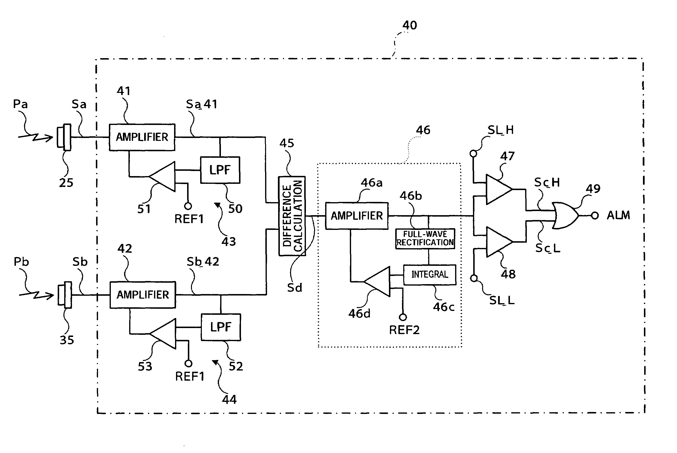
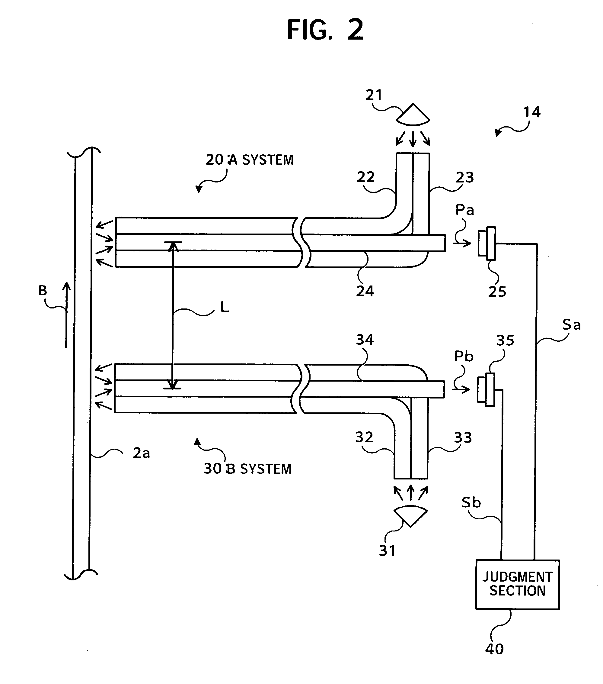
The present invention is a metal surface inspection device for metal rings of a Continuously Variable Transmission (CVT) V-belt. The device includes a light source for illuminating the surface of the metal ring, a light guiding path for guiding reflected light from the surface to a detector, and a difference value calculation means for calculating the difference between the electrical signals outputted from the two detectors. The device also includes a discrimination means for discriminating any defects on the surface of the metal ring and comparing the difference value with a predetermined threshold value. The difference value is corrected based on an integral value calculation and a difference value correction means is used to prevent excessive detection of mackerel skins, which are flaws that are continuous or with a certain amount of length. The device can effectively detect and locate defects on the metal surface, improving the quality and efficiency of the manufacturing process.

Problems solved by technology

However, in this antiquated method there is the drawback of being inefficient due to the fact that human error rate is always higher than an automated process.
Thus, satisfactory reproducibility and reliability are not routinely acquired.
However, although the above-mentioned conventional prior art is a beneficial device from the viewpoint of being able to automatically discriminate whether or not a defect exists on an inspectable surface, there is a drawback in which the inspection process excessively detects for example “mackerel skins” as manufacturing defects which do not impair the durability of the metal belt.
Thus, it is a waste of resources to exclude metal rings which have such a mackerel skin as a defective part and not preferred in terms of manufacturing cost.

Method used


Image

  • Metal surface inspection device for metal rings of a continuously variable transmission belt
  • Metal surface inspection device for metal rings of a continuously variable transmission belt
  • Metal surface inspection device for metal rings of a continuously variable transmission belt

Examples


Embodiment Construction

[0028]The preferred embodiments of the present invention will hereinafter be described in detail with reference to the drawings. Additionally, in the following explanation of specific or examples of various details, numerical values or character strings and other illustrative symbols are merely references to clarify the concept of the present invention. Accordingly, the concept of the present invention should not be limited explicitly to this terminology entirely or in part.

[0029]In addition, explanation is omitted which describes details of well-known methods, well-known procedures, well-known architecture, well-known circuit configurations, etc. (hereinafter referred to as “common knowledge”) for the purpose of concise explanation, but does not intentionally exclude this common knowledge entirely or in part. Therefore, relevant common knowledge which is already known by persons skilled in the art at the time of filing the present invention is included in the following description....


PUM

PropertyMeasurementUnit
thicknessaaaaaaaaaa
electricalaaaaaaaaaa
surface inspectionaaaaaaaaaa

Abstract

A metal surface inspection device for metal rings of a Continuously Variable Transmission (CVT) V-belt which does not perform excessive detection of mackerel skins as a detrimental manufacturing flaw. This task is achieved by providing an “integral value calculation portion” for calculating an integral value of a difference value and a “difference value correction portion” for correcting the difference value in a decreasing direction as the integral value increases. When mackerel skins contained on an inspectable surface are detected the output (integral value of the difference value) of the integral value calculation portion increases. Accordingly, the difference value is corrected in a decreasing direction which enables the operation to control the signal of the mackerel skin portions and threshold values are not exceeded which prevents excessive detection.

Description

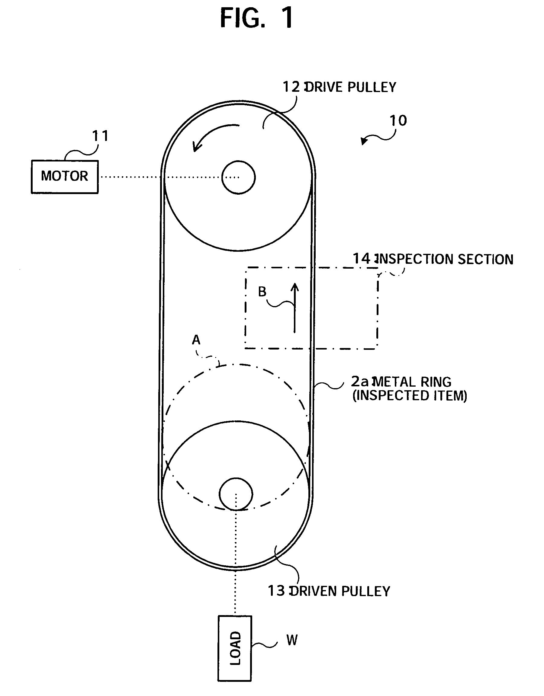
BACKGROUND OF THE INVENTION[0001]1. Field of the Invention[0002]The present invention relates to a metal surface inspection device. More particularly, the present invention relates to a metal surface inspection device suitable for use in inspecting the surface of metal rings which are parts that constitute a V-belt type of a Continuously Variable Transmission belt (hereinafter referred to as “CVT belt”).[0003]2. Description of the Related Art[0004]Conventionally, there is a known CVT belt structure which laminates a plurality of thin metal rings in a stack of approximately 0.2 mm in thickness to which steel elements are consecutively attached.[0005]FIG. 5 is an outline view of a CVT belt. In this diagram, a CVT belt 1 is constructed by assembling two laminated bands of a layered belt 2 that contain a stack of a number of metal rings 2a (for example, a laminated band composed of about 12 endless layers) which are supported by a layered element 3 composed of a large number of steel el...

Claims


Application Information

Patent Timeline
Patent Type & Authority Patents(United States)
IPC IPC(8): G01B5/28G01B5/30F16G5/16G01N21/892G01N21/89G01N21/95
CPCF16G5/16
Inventor TANGE, HIROSHISUZUKI, USHIO
Owner JATCO LTD
Learn More