
Videotape recording and playback device, and videotape player

Inactive Publication Date: 2006-08-15
SONY CORP
View PDF25 Cites 12 Cited by
  • Summary
  • Abstract
  • Description
  • Claims
  • Application Information

AI Technical Summary

Benefits of technology

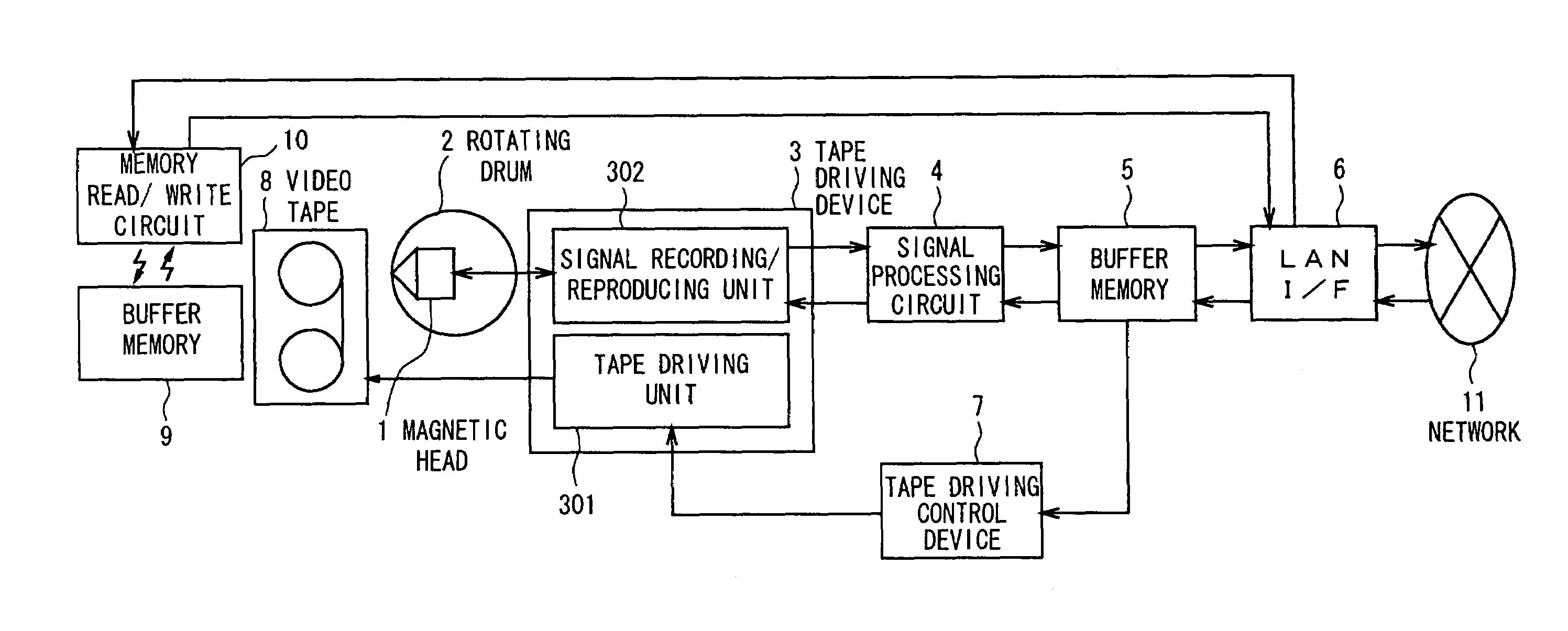
[0007]It is therefore an object of the present invention to provide a video tape recording / reproducing device capable of alleviating the specification requirements and diminishing the load on the network and the video server.
[0009]Moreover, as a preferred embodiment such as described in Claim 2, in the video tape recording / reproducing device according to Claim 1, the driving control means controls the running speed of said video tape by said driving means, and when the data quantity stored in the buffer memory is larger than the proper value, it controls said driving means to lower the running speed of said video tape. While, when the data quantity stored in the buffer memory is smaller than the proper value, it controls said driving means to increase the running speed of said video tape.
[0014]Furthermore, as another preferred embodiment such as described in Claim 7, the video tape reproducing device according to Claim 6, wherein said driving control means controls the running speed of said video tape by said driving means, and controls said driving means so that when the data quantity stored in said buffer memory is larger than the proper value, the video tape running speed is lowered, while when the data quantity stored in said buffer memory is smaller than the proper value, the video tape running speed is increased.
[0016]According to the present invention, the video data to be reproduced while the video tape is being moved by the driving means are stored temporarily in the buffer memory and then delivered to an external equipment via the interface. Or the video data put in from the external equipment via the interface are stored temporarily in the buffer memory and then the video data are recorded on the video tape to be moved by the driving means. At this point, the driving control means controls the video tape transfer rate by said driving means in accordance with the data quantity stored in the buffer memory. Accordingly, the reproduction / recording of the video data can be performed by automatic adjusting the tape driving speed according to the transmission speed of the network without using any external memory device such as a hard disk. Thereby, it becomes possible to alleviate the specification requirements and diminish the load of the network and the video server.

Problems solved by technology

Consequently, there have been problems in the conventional system, including that the cost is increased and the specification requirements relative to the network and the storage device of the video server are rendered stricter.
And such external memory devices have led to the cost increase.
However, in the video tape recording / reproducing device, since the video tape is a sequential access recording medium, it took time for forming, detecting and referring to such list.

Method used


Image

  • Videotape recording and playback device, and videotape player
  • Videotape recording and playback device, and videotape player
  • Videotape recording and playback device, and videotape player

Examples


embodiment

B. OPERATION OF EMBODIMENT

[0042]Next, the operation of the embodiment described above will be explained in the following paragraphs.

[0043]Firstly, the operation in the case of reproducing the contents of video tape and transmitting via the LAN interface 6 will be explained. When the video tape is reproduced by the tape driving device 3, signals read in (audio-visual signals) are supplied to the signal processing circuit 4 and outputted as compressed video signals. At this point, even if the video tape is driven more slowly than in the recording mode and the magnetic head 1 is kept scanning the same recording track on the video tape repeatedly, the signal processing circuit 4 would not output the same signal twice or more.

[0044]In the signal processing circuit 4, the audio-video data are transmitted collectively in units of GOP to the buffer memory 5. Since in the tape driving device 3 the data of each GPO are recorded in a plurality of helical tracks as long as the video tape is mov...


PUM


Abstract

The object of the present invention is to reduce the load and specification requirements on the network and the video server. The buffer usage rate is counted and supplied to the tape driving controller 7. In the reproduction mode, the tape driving controller 7 decreases the running speed of a video tape when the buffer usage rate is larger than the proper value. And when the buffer usage rate is smaller than the proper value, the tape driving controller 7 increases the running speed of the video tape. Moreover, in the recording mode, the tape driving controller 7 stops the tape motion temporarily if the transmission speed of the network is slow and the buffer usage rate declines lower than the proper value. And if the buffer usage rate increases over the proper value, the tape driving controller 7 resumes the tape driving to record signals. Thus, the reproduction speed or the recording speed by the tape driving device 3 can be coincided with the transmission speed of the network.

Description

TECHNICAL FIELD[0001]The present invention relates to a video tape recording / reproducing device for recording video data on a video tape and reproducing the video data recorded on the video tape.BACKGROUND ART[0002]In recent years, video servers (or AV (audio and video) servers) which perform nonlinear recording and reproduction by using a random accessable recording medium have come into widespread use in place of sequential (linear) recording and reproduction using a VTR tape. In general, in order to comply with demands for high image quality and sound quality, a video server employed as an equipment in the broadcasting station is required to achieve a high data transfer rate and a large storage capacity for enabling long-time data recording. Thus, material data composed of a plurality of audio-video data are dispersely recorded by using the RAID (Redundant Arrays of Inexpensive Disks) which is comprised of multiple hard disks adapted for time-division recording and reproduction a...

Claims


Application Information

Patent Timeline
IPC IPC(8): G11B5/09G11B5/008G11B5/53G11B15/02G11B15/07G11B15/12G11B15/18G11B15/20G11B15/46G11B15/467G11B15/52H04N5/7826
CPCH04N5/78263G11B15/026G11B15/07G11B15/52G11B15/1875G11B15/20G11B15/46G11B15/4673G11B15/125G11B5/0086G11B5/534G11B15/385G11B2020/1062G11B2220/90
Inventor YOSHIHIRO, MITSUGU
Owner SONY CORP
Learn More