Nitride semiconductor device and manufacturing method thereof
a technology of nitride semiconductor and manufacturing method, which is applied in the direction of semiconductor lasers, crystal growth process, polycrystalline material growth, etc., can solve the problems of large cracks in nitride semiconductor layers grown on gan substrates, too small cracks to observe by a typical optical microscope, and desired long life, etc., to achieve prevent breakage and chipping of wafers, reduce the size of chips, and good heat radiation characteristics
- Summary
- Abstract
- Description
- Claims
- Application Information
AI Technical Summary
Benefits of technology
Problems solved by technology
Method used
Image
Examples
example 1
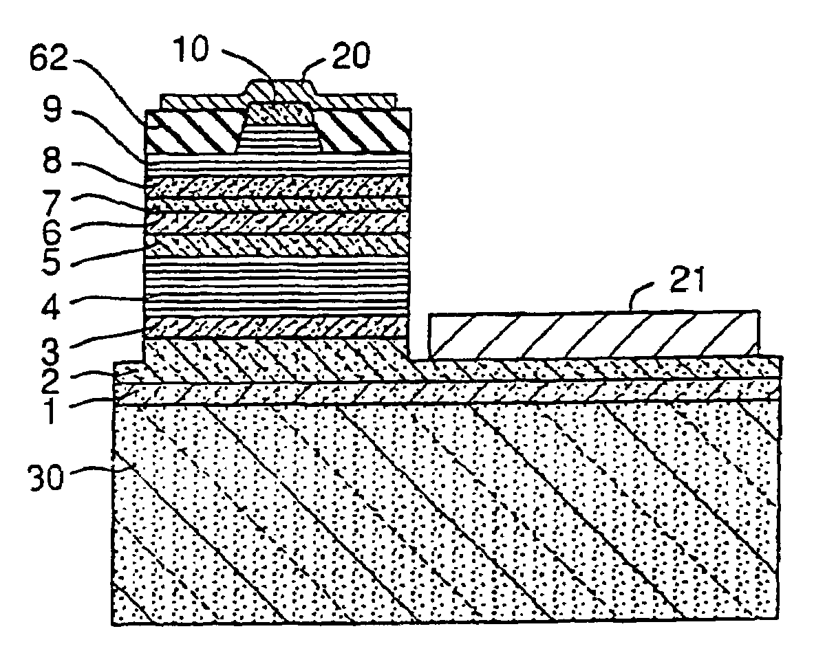
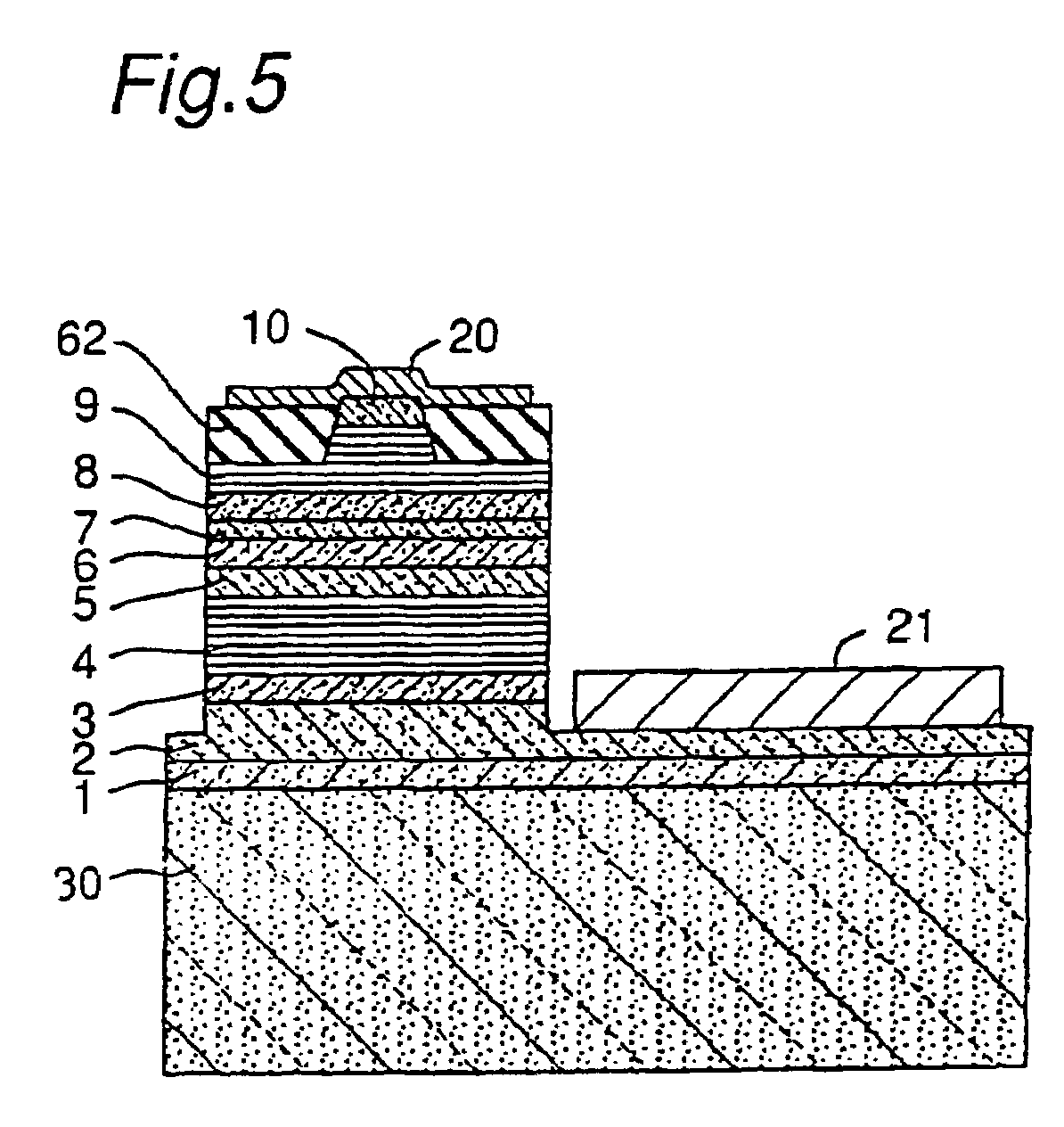
[0053]In Example 1, the nitride semiconductor laser device as shown in FIG. 5 was manufactured.
(Manufacturing Method of the GaN Substrate)
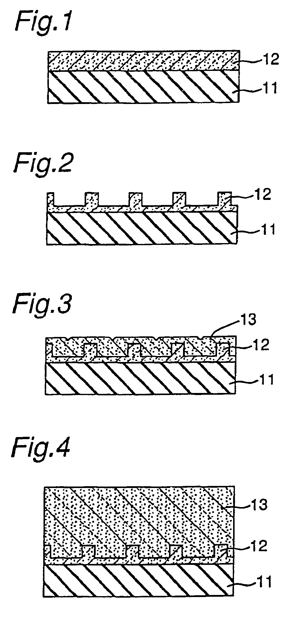
[0054]The GaN substrate was manufactured according to each step as shown in FIGS. 1 to 4.
[0055]A sapphire substrate 11 of two-inch in diameter having its principal surface represented by a C-face and an orientation flat face represented by an A-face was set in the reactor and the temperature was adjusted to 510° C. A buffer layer (not shown) made of GaN which has a thickness of about 200 angstroms was grown using hydrogen as a carrier gas and ammonia and TMG (trimethylgallium) as a source of GaN on the sapphire substrate.
[0056]After growing the buffer layer, only TMG was stopped and the temperature was increased to 1050° C. At 1050° C., using ammonia and TMG as a source of GaN, a first nitride semiconductor layer 12 made of undoped GaN was grown to the thickness of 2 μm (FIG. 1).
[0057]After growing a first nitride semiconductor layer 12, a photo-m...
example 2
[0084]The laser device was fabricated in the same manner as in Example 1, except that the undoped n-type contact layer 1 was not grown and only the n-type contact layer 2 was grown.
[0085]The resulting device had a crystallinity which was a little worse than that in Example 1. But small cracks could be prevented almost like in Example 1 and good device characteristics could be achieved.
example 3
[0086]The laser device was fabricated in the same manner as in Example 1, except that the ratio of Al in the undoped n-type contact layer 1 and the Si-doped n-type contact layer 2 was changed from 0.05 to 0.2.
[0087]The resulting device showed good result almost like in Example 1.
PUM
| Property | Measurement | Unit |
|---|---|---|
| thickness | aaaaa | aaaaa |
| thickness | aaaaa | aaaaa |
| thickness | aaaaa | aaaaa |
Abstract
Description
Claims
Application Information
 - R&D
- Intellectual Property
- Life Sciences
- Materials
- Tech Scout
- Unparalleled Data Quality
- Higher Quality Content
- 60% Fewer Hallucinations
Browse by: Latest US Patents, China's latest patents, Technical Efficacy Thesaurus, Application Domain, Technology Topic, Popular Technical Reports.
© 2025 PatSnap. All rights reserved.Legal|Privacy policy|Modern Slavery Act Transparency Statement|Sitemap|About US| Contact US: help@patsnap.com


