
Electrode and electrode holder with threaded connection

a technology of electrode holder and thread connection, which is applied in plasma technique, welding apparatus, manufacturing tools, etc., can solve the problems of undesired arcing within the torch, limited life of the electrode holder, and limited nozzle geometry of the nozzl

Active Publication Date: 2006-07-25
THE ESAB GROUP
View PDF23 Cites 32 Cited by
  • Summary
  • Abstract
  • Description
  • Claims
  • Application Information

AI Technical Summary

Benefits of technology

[0020]According to one inventive aspect of the threaded connection of the present invention, the crests of the male thread are narrower than the roots of the male thread. This can be geometrically defined by saying that the nominal pitch diameter of the electrode is not greater than the minor diameter of the electrode. In another, the nominal pitch diameter of the electrode is smaller than the minor diameter of the female thread of the electrode holder. In a conventional thread, the nominal pitch diameter as defined herein would be closer to or at the midpoint between the minor and major diameters of the respective components. Another advantage of the present invention is that the electrode holder can be held to the plasma arc torch body by a male thread at the opposite end from the electrode, which male thread corresponds at least in shape to the male thread of the electrode and provides similar advantages inasmuch as the electrode holder can also be consumable, at least relative to the plasma arc torch body.
[0021]Another way of defining the novel threaded connection of the electrode and the electrode holder that embodies the benefits of the invention is to recognize that each defines a mean diameter between the major diameter and the minor diameter. As such, a crest portion extends in one direction from the mean diameter, and a root area extends in an opposite direction from the mean diameter and defines a width along the mean diameter. Advantageously, the width of the root area of the thread of the electrode is wider than the width of the root area of the thread of the electrode holder, and in particular is at least about 35% wider. The root area of the electrode may be at least about 45% wider than the root area of the electrode holder, and further can be at least about 55% wider than the root area of the electrode holder. In addition, with regard to the threaded portion of the electrode, the width of the root area is greater than the width of the crest portion by at least 15%, and can be at least about 55% greater than the width of the crest portion, and may be 95% wider or more.
[0022]Thus, the present invention solves the problems recognized above in that the novel threaded connection provides for the more-consumable electrode to be formed with less material relative to the electrode holder. Some electrodes can be made much shorter as compared to conventional electrodes for corresponding torches. In addition, any threading damage or wear as between the electrode and electrode holder is less likely to be suffered by the less consumable of the two parts, the electrode holder. Advantageously, the present invention also provides for an electrode and electrode holder threaded engagement to be positioned at least partially within the nozzle chamber of the torch with the male thread on the electrode.

Problems solved by technology

Even with the water-cooling, the electrode has a limited life span and is considered a consumable part.
Third, a considerable current is passed through the electrode holder to the electrode, in some cases up to 1,000 amperes of cutting current.
However, the length of the electrode holder is limited by the nozzle geometry because the threaded connection between the electrode holder and the electrode in many conventional torches is too large to extend into the nozzle chamber and still meet the design constraints noted above.
Thus, the decrease in the gap might cause undesired arcing within the torch from the nozzle to the electrode holder.
One disadvantage of this approach, however, is that female threads are generally more difficult to machine and thus are more expensive than male threads.
Even though the electrode holder can sometimes be a consumable part, the rate of consumption is typically less than that of the electrode, and thus this configuration can have an undesirable cost structure.
The more frequently replaced part must be subjected to the more expensive of the two machining operations necessary for making a threaded connection.
However, fine threads are more difficult to machine and thus can be more expensive.
In addition, fine threads are more delicate, are quicker to become unusably worn on the electrode holder when electrodes are repeatedly replaced, and are more likely to be improperly cross-threaded when an operator is installing a new electrode.

Method used


Image

  • Electrode and electrode holder with threaded connection
  • Electrode and electrode holder with threaded connection
  • Electrode and electrode holder with threaded connection

Examples


Embodiment Construction

[0036]The present invention now will be described more fully hereinafter with reference to the accompanying drawings, in which some, but not all embodiments of the invention are shown. Indeed, these inventions may be embodied in many different forms and should not be construed as limited to the embodiments set forth herein; rather, these embodiments are provided so that this disclosure will satisfy applicable legal requirements. Like numbers refer to like elements throughout.

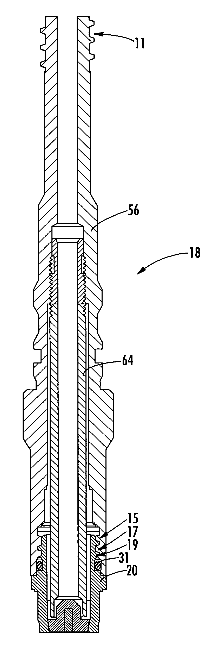
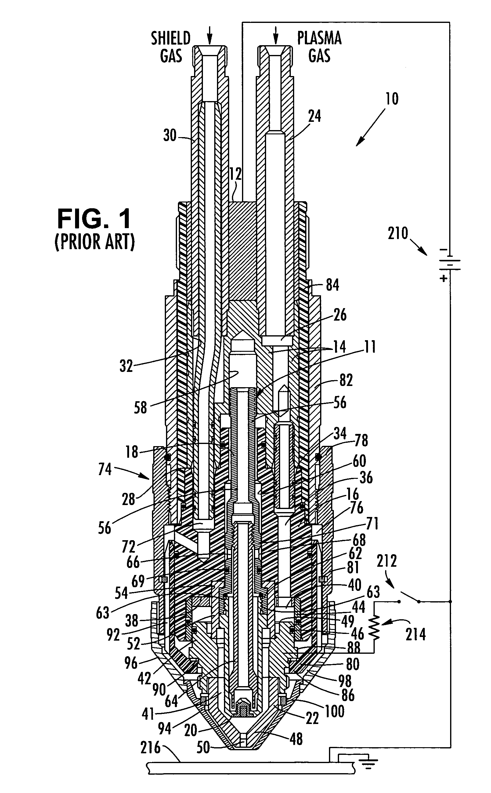
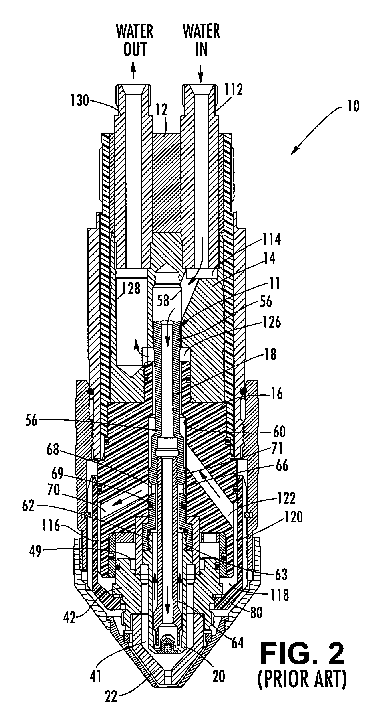
[0037]With reference to FIGS. 1–3, a prior plasma arc torch that benefits from the invention is broadly indicated by reference numeral 10. A plasma arc torch 10 using an electrode and electrode holder according to the present invention is illustrated in FIG. 4. The torch 10 is a shielding gas torch, which provides a swirling curtain or jet of shielding gas surrounding the electric arc during a working mode of operation of the torch. The torch 10 includes a generally cylindrical upper or rear insulator body 12 wh...


PUM

PropertyMeasurementUnit
cutting currentaaaaaaaaaa
included angleaaaaaaaaaa
diameteraaaaaaaaaa

Abstract

A threaded connection for an electrode holder and an electrode in a plasma arc torch is provided. The threaded connection has relatively low height, and the engaged portion of a male threaded portion of the electrode and a female threaded portion of the electrode holder are positioned at least partially within a nozzle chamber. In one inventive aspect, the nominal pitch diameter of the electrode is less than the minor diameter of the electrode. In another, the width of the root area of the electrode thread is wider than the width of the root area of the electrode holder thread by at least about 35%. The width of the root area of the electrode is at least about 15% wider than the width of the crest portion of the electrode. As such, the less consumable of the two parts, the electrode holder, is provided with a thread that is less likely to be worn and damaged. In one particular embodiment, the crest profile of the electrode is that of a Stub Acme thread separated by a larger root profile.

Description

BACKGROUND OF THE INVENTION[0001]1) Field of the Invention[0002]The present invention relates to plasma arc torches and, in particular, to plasma arc torches wherein an electrode and an electrode holder are held to each other or to the torch by way of a threaded connection.[0003]2) Description of Related Art[0004]Plasma arc torches are commonly used for the working of metal including cutting, welding, surface treatment, melting and annealing. Such torches include an electrode that supports an arc that extends from the electrode to a workpiece in a transferred-arc mode of operation. It is also conventional to surround the arc with a swirling vortex flow of gas, and in some torch designs it is conventional to also envelop the gas and arc in a swirling jet of water.[0005]The electrode used in conventional torches of the described type typically comprises an elongate tubular member composed of a material of high thermal conductivity, such as copper or copper alloy. The forward or discha...

Claims


Application Information

Patent Timeline
Patent Type & Authority Patents(United States)
IPC IPC(8): B23K9/00
CPCH05H1/34Y10T403/556Y10T29/49117H05H2001/3478H05H1/3478
Inventor SEVERANCE, JR., WAYNE STANLEY
Owner THE ESAB GROUP
Learn More