
Hybrid battery power source for implantable medical use

a hybrid battery and medical device technology, applied in primary cell maintenance/service, non-aqueous electrolyte cells, therapy, etc., can solve the problems of significant voltage delay, and li/svo cell resistance increase unpredictable, etc., to optimize the output, and improve the efficiency of the cell

Inactive Publication Date: 2006-07-18
GENTCORP
View PDF36 Cites 38 Cited by
  • Summary
  • Abstract
  • Description
  • Claims
  • Application Information

AI Technical Summary

Benefits of technology

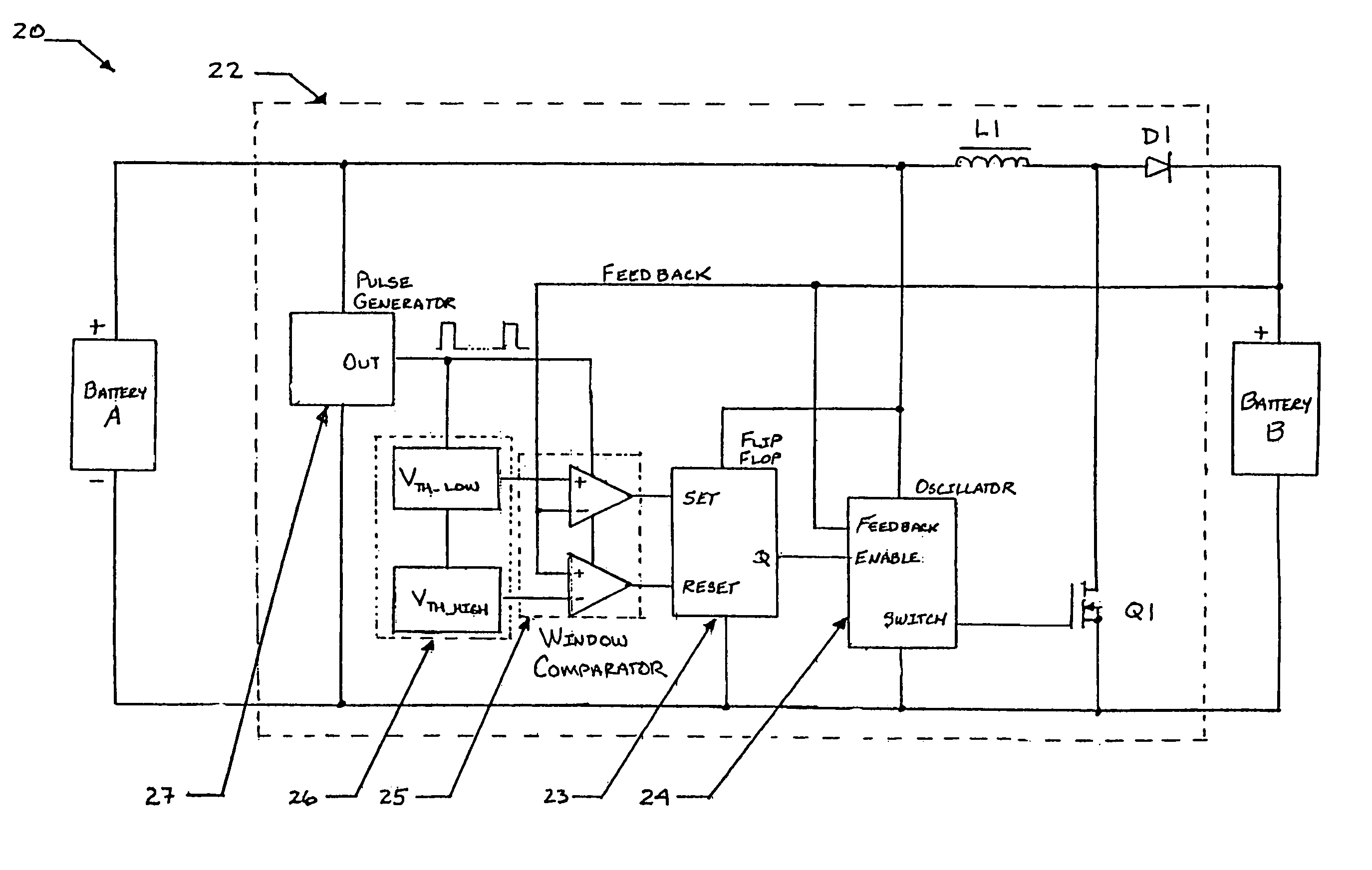
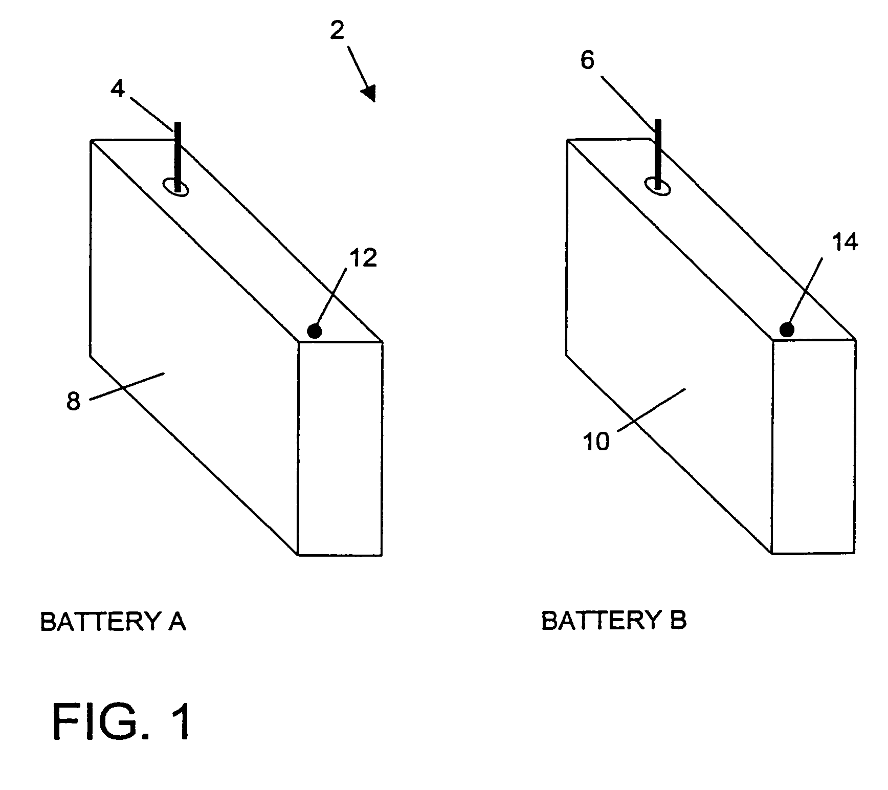
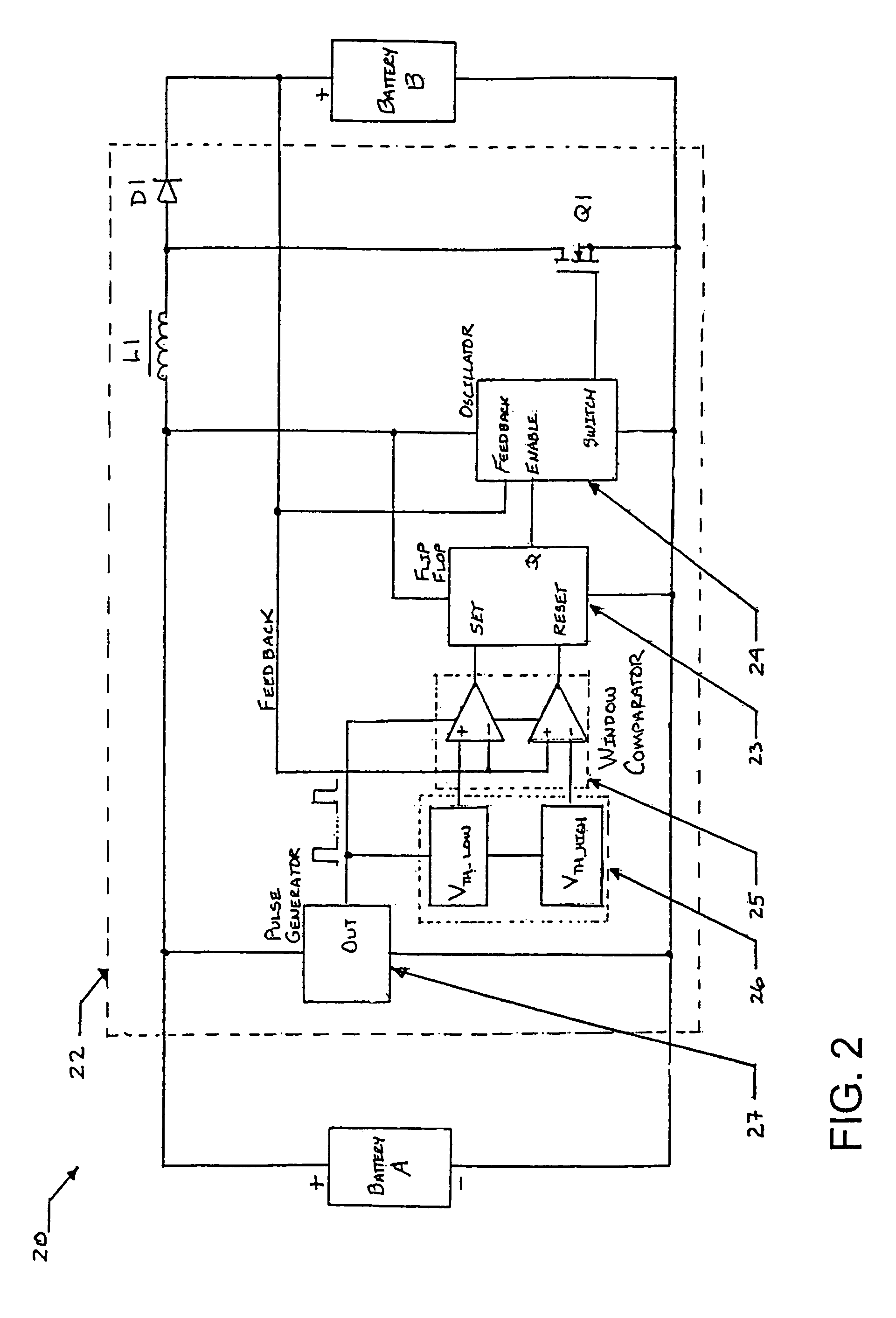
[0014]In exemplary embodiments of the invention, the power source utilizes two batteries, each of which may comprise one or more cells. The first battery is a primary (nonrechargeable) battery of relatively high energy density. The second battery is a secondary (rechargeable) battery whose internal resistance is relatively low and stable over time. The primary battery and the secondary battery are connected in a parallel arrangement via a charge control circuit. The charge control circuit may include a voltage boost function and is adapted to limit the charge / discharge excursions and control the recharging rate of the secondary battery in a manner that optimizes its output for high energy medical device use.
[0015]It is therefore an object of the present invention to minimize the effect of the change in internal resistance as a battery for implantable medical use discharges during service.
[0016]A further object of the invention is to add a secondary power segment having low internal resistance and relatively constant terminal voltage to an implantable power source that will provide a source for rapid charging of energy storage capacitors used to deliver high energy impulses.

Problems solved by technology

Unfortunately, as noted by Crespi, a Li / SVO cell can experience unpredictable resistance increase upon long-term discharge service.
In many cases, the voltage delay experienced by a Li / SVO cell is significant enough to impair the cell's ability to charge the capacitors of a defibrillator or ICD in a timely manner.
This may result, prematurely, in a decision being made that the Li / SVO cell has reached end of service (EOS) and needs to be explanted for replacement.
In addition to the patient inconvenience and risk entailed by the explantation procedure, a significant portion of the capacity of the Li / SVO cell is needlessly rendered unavailable for long-term use.
Even if it is not removed, the cell's operation is unpredictable, thus making any attempt to calculate the EOS point rather complicated.
This energy density disadvantage requires the use of a battery with greater volume and weight than would otherwise be needed if the Li / CFx or Li / I cells could be used.
However, the Li / CFx and Li / I cells are unsuitable for the described applications because they cannot support the rapid discharge rates required for charging the defibrillator capacitors.
The Li / SVO cell has the added disadvantage of significantly higher cost when compared to the Li / CFx and Li / I chemistries.
A shortcoming of the rechargeable battery system is that the lithium-based battery chemistries proposed for the secondary energy stage are not all suitable for the proposed application.
One is an LiMnO2 system, but this is a primary system and is not suited to recharging.
Another is an LiSO2 system, but this operates with a sealed cell at a pressure of 3 to 6 atmospheres and is not suited for high-rate discharge applications.

Method used


Image

  • Hybrid battery power source for implantable medical use
  • Hybrid battery power source for implantable medical use
  • Hybrid battery power source for implantable medical use

Examples


Embodiment Construction

Introduction

[0032]Exemplary hybrid battery power sources for use with implantable defibrillators, ICDs and other high energy battery powered medical devices will now be described, together with an exemplary defibrillator that incorporates a hybrid battery power source therein. As indicated by way of summary above, the power source embodiments disclosed herein are characterized by having primary and secondary batteries. The primary battery has high energy density but typically will also have internal resistance that is relatively high, or which can increase significantly during discharge. Examples of this primary battery include the lithium-carbon monofluoride (Li / CFx) battery, the lithium-bromine chloride (Li / BrCl2) battery, the lithium sulfuryl chloride (Li / SO2Cl2) battery, the lithium thionyl chloride (Li / SOCl2) battery, the lithium-manganese dioxide battery (Li / MnO2), and the lithium-silver vanadium oxide (Li / SVO) battery. The secondary battery is rechargeable and has low interna...


PUM

PropertyMeasurementUnit
volumetric energy densityaaaaaaaaaa
pressureaaaaaaaaaa
open circuit voltageaaaaaaaaaa

Abstract

A hybrid battery power source for implantable medical use provides a generally constant low internal resistance during discharge and avoids voltage delays of the type that develop as a result of run down-induced resistance increase in Li / SVO cells. The hybrid battery power source utilizes two batteries or cells, one being a primary cell of relatively high energy density and the other being a secondary cell of relatively low internal resistance that is rechargeable. The primary and secondary cells are connected in a parallel arrangement via a voltage boost / charge control circuit that is powered by the primary cell and adapted to charge the secondary cell while limiting charge / discharge excursions thereof in a manner that optimizes its output for high energy medical device use. The energy storage capacitors of the medical device in which the hybrid battery power source is situated are driven by the secondary cell. The primary cell is used to as an energy source for recharging the secondary cell.

Description

CROSS-REFERENCE TO RELATED APPLICATIONS[0001]This application is a continuation-in-part of U.S. patent application Ser. No. 10 / 727,349, filed on Dec. 3, 2003 and entitled “Improved Hybrid Battery Power Source For Implantable Medical Use,” which is a continuation-in-part of U.S. patent application Ser. No. 10 / 407,916, filed on Apr. 4, 2003 and entitled “Hybrid Battery Power Source For Implantable Medical Use,” which is a continuation-in-part of U.S. patent application Ser. No. 10 / 350,921, filed on Jan. 24, 2003 now U.S. Pat. No. 6,909,915 and entitled “Hybrid Battery Power Source For Implantable Medical Use.”BACKGROUND OF THE INVENTION[0002]1. Field of the Invention[0003]The present invention relates to improvements in the performance of implantable defibrillators, implantable cardioverter-defibrillators (ICDs) and other battery powered medical devices designed to provide high energy electrical stimulation of body tissue for therapeutic purposes.[0004]2. Description of Prior Art[0005...

Claims


Application Information

Patent Timeline
Patent Type & Authority Patents(United States)
IPC IPC(8): A61N1/40A61N1/08A61N1/378H01M6/16H01M6/50H01M10/052H01M10/0525H01M16/00H02J7/00
CPCA61N1/08A61N1/378H01M6/16H01M10/0525H01M16/00H02J7/0054H01M6/5033H01M6/5016Y02E60/122H01M10/052H02J7/342Y02E60/10H02J2310/23
Inventor GREATBATCH, WILSONDEAL, JEFFREY
Owner GENTCORP
Learn More