
Receiver apparatus controlling the power consumption according to the reception signal level

a technology of receiving apparatus and power consumption, applied in the field of receiving apparatus, can solve the problems of large power consumption, achieve the effect of reducing the power consumption of the receiving section, and reducing the demodulation quality

Inactive Publication Date: 2006-07-11
HITACHI LTD
View PDF12 Cites 25 Cited by
  • Summary
  • Abstract
  • Description
  • Claims
  • Application Information

AI Technical Summary

Benefits of technology

[0016]And the power detected by the power detectors (RSSIs) 206 and 207 are compared in a comparator 108, and a difference or a ratio of both power is calculated, and in a decision device (DECISION) 209, an interference wave level inputted to the receiver section is estimated in accordance with a predetermined algorithm. A control signal output from the decision device 209 is delayed by one frame or one slot in a delay element 210, and by supplying the delayed control signal to the low noise amplifier 200 and the mixer 201, a bias current of the circuit of the low noise amplifier 200 and the mixer 201 is changed over. By controlling this bias current, the dynamic range of the low noise amplifier 200 and the mixer 201 are controlled. For example, when the interference wave level is large, the bias current of the low noise amplifier 200 and the mixer 201 is increased, to thereby enlarge the dynamic range. Generally, in the low noise amplifier 200 and the mixer 201, by increasing their bias current, the dynamic range can be made wide. Also, when the interference wave level is small, since it is allowed to make the dynamic range narrow, the bias current of the low noise amplifier 200 and the mixer 201 is decreased. As mentioned above, by changing the dynamic range according to the estimated interference wave level, it is possible to reduce the mean power consumption of the receiver section.
[0029]Also, the amplifying stage includes a plurality of pre-amplifiers provided in parallel, and an adder for adding outputs of the pre-amplifiers, and the signal processing section controls the number of the plurality of pre-amplifiers which are to be operated. As a result, in the case where the received signal level is large, and the carrier-to-noise ratio (CN) value at the receiver section output is excessively good as compared with a desired level, since it is possible to reduce the power consumption of the receiver section by controlling a phase noise level of the local oscillator while maintaining the dynamic range of the frequency converting stage, it is possible to reduce the power consumption without causing deterioration of the demodulation quality due to the interference wave.

Problems solved by technology

The problem in the receiver section of the direct conversion system shown in FIG. 11 is that the power consumption becomes large.

Method used


Image

  • Receiver apparatus controlling the power consumption according to the reception signal level
  • Receiver apparatus controlling the power consumption according to the reception signal level
  • Receiver apparatus controlling the power consumption according to the reception signal level

Examples


first embodiment

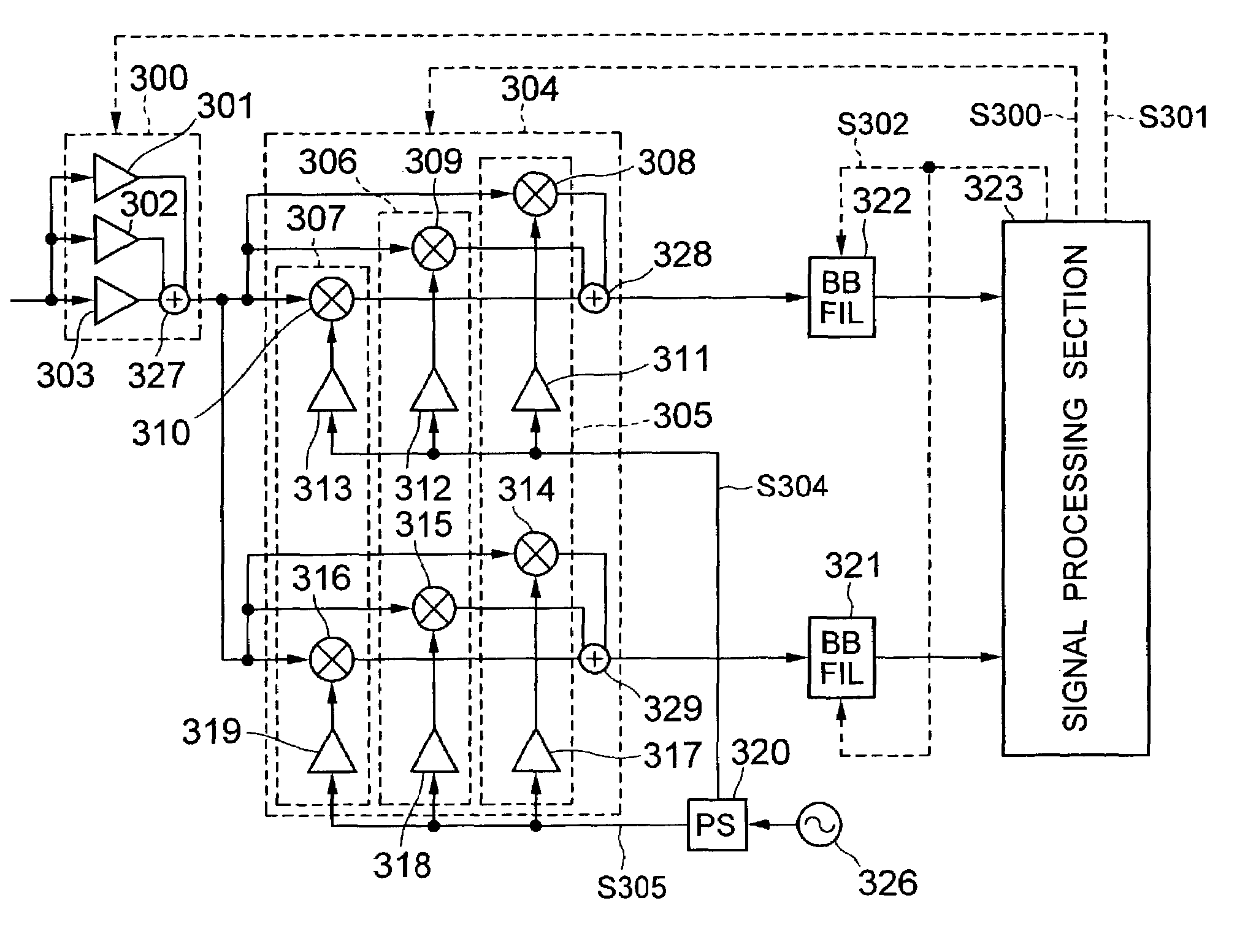
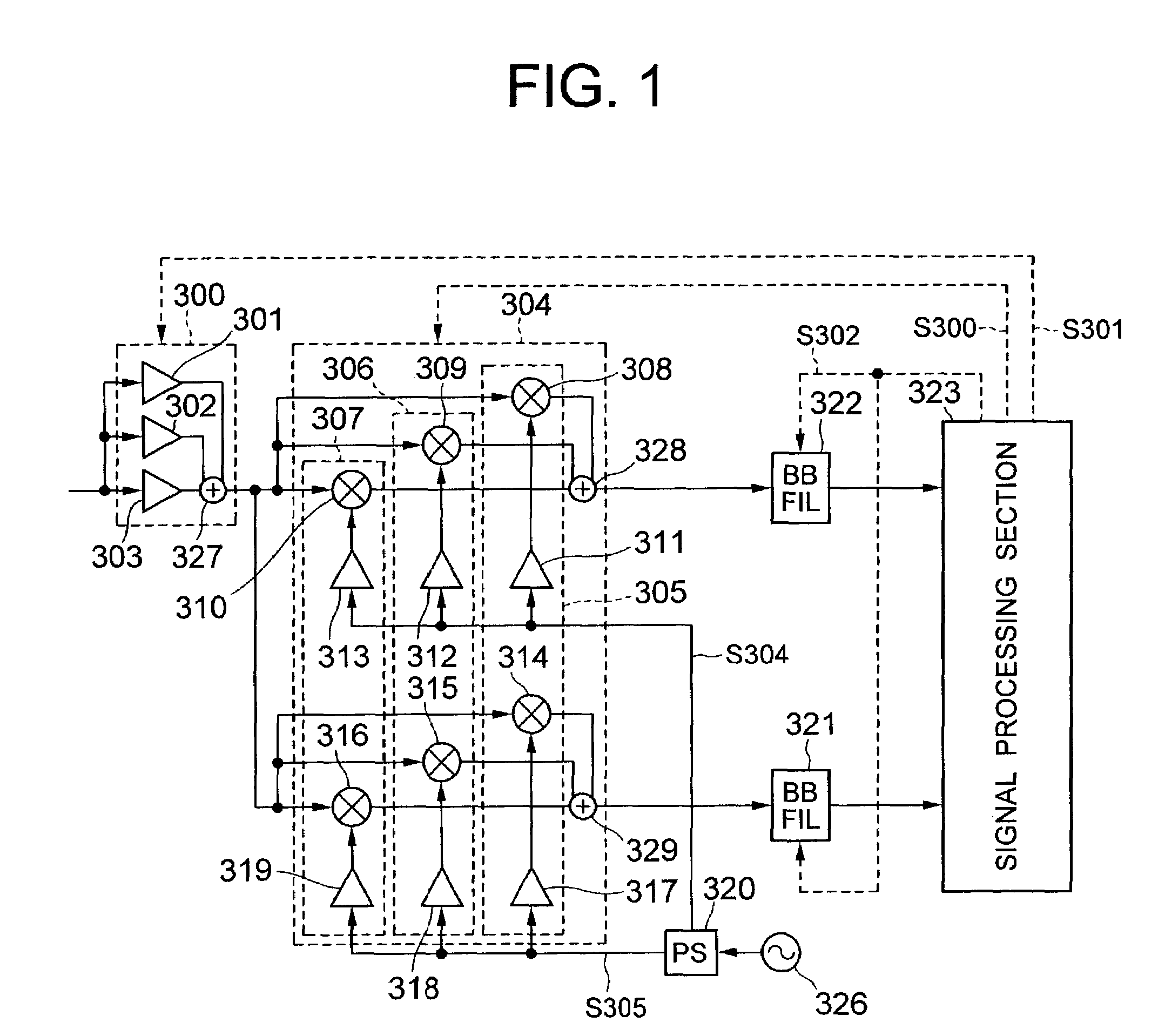
[0045]FIG. 1 is a block diagram showing a constitution of a low power consumption receiver section in the present invention.

[0046]The receiver section shown in FIG. 1 is a receiver section of the direct conversion system, and includes a low noise amplifying stage 300 for giving a desired gain to a high frequency signal which is received, a frequency converting stage 304 for frequency converting an output signal of the low noise amplifying stage 300 to a base band signal, base band filters (BB FIL) 321 and 322 for selecting a signal of a desired frequency and giving a gain, a local oscillator 326, a phase shifter (PS) 320 for converting an output signal of the local oscillator 326 to signals having phases shifted by 90 degrees from each other, and supplying to the frequency converting stage 304, and a signal processing section 323. The gain of a variable gain amplifier included in each of the base band filters (BB FILs) 321 and 322 is controlled by a control signal S302 from the sign...

fifth embodiment

[0077]FIG. 5 is a block diagram showing a constitution of a low power consumption receiver section in the present invention.

[0078]The receiver section shown in FIG. 5 is a receiver section of the digital-IF system, and includes: a low noise amplifying stage 300 for giving a desired gain to a received high frequency signal, a banspass filter (BPF) 500 for suppressing an undesired signal from an output signal of the low noise amplifier 300, a frequency converting stage 612 for converting a frequency of an output signal of the bandpass filter 500 to a fourth intermediate frequency, a bandpass filter (BPF) 615 for suppressing an undesired signal from an output signal of the frequency converting stage 612, a variable gain amplifier 700 for giving a desired gain to an output signal of the BPF 615, a local oscillator 614 for supplying a local oscillating signal (local signal) to the frequency converting stage 612, and a signal processing section 323. In this respect, constituent elements o...

sixth embodiment

[0083]FIG. 6 is a block diagram showing a constitution of a low power consumption receiver section in the present invention.

[0084]The receiver section shown in FIG. 6 is a receiver section of the image rejection system, and includes: a low noise amplifying stage 300 for giving a desired gain to a received high frequency signal, a frequency converting stage 820 for converting a frequency of an output signal of the low noise amplifying stage 300 to a fifth intermediate frequency, phase shifters 822 and 823 for converting phases of output signals S801 and S802 of the frequency converting stage 820, an adder 824 for adding output signals of the phase shifters 822 and 823, a bandpass filter 615 (BPF) 615 for passing only a signal of a desired frequency of an output signal of the adder 824, and for suppressing an undesired undesired signal, a demodulator (DEM) 532 for frequency converting an output signal of the BPF 615 to a base band signal, a local oscillator 821 for supplying a local s...


PUM


Abstract

A receiver apparatus is provided with a receiver section including an amplifying stage for amplifying a high frequency signal received by an antenna, a frequency converting stage for converting a frequency of the output signal of the amplifying stage, a local oscillator for supplying a local oscillating signal to the frequency converting stage, and a signal processing section for supplying a control signal to the receiver section depending on signal intensity inputted to the receiver section, or to the signal processing section from the receiver section. The frequency converting section includes a plurality of parallel frequency converters, and an adder for adding output signals of the frequency converters. The signal processing section controls the number of the frequency converters to be operated.

Description

BACKGROUND OF THE INVENTION[0001]The present invention relates to a receiver apparatus used in a mobile communication system such as a portable telephone, and in particular, to a receiver apparatus with reduced power consumption.[0002]The services originally provided to users by a mobile communication system have been primarily an audio communication, however, recently the function has been progressed to a higher degree in which a data communication is capable. Corresponding to this, large parts consuming much power such as an FM sound source and a large type display device have been mounted on a terminal. Because of this, it has been requested to further reduce the power consumption of the parts constituting the terminal. The receiver section of the direct conversion system is described, for example, in Behazad Razavi “RF MICROELECTRONICS”, PRENTICE HALL PTR, pp. 122–129, 138–144, 146–147 and 209–231, or JP-A-10-256930 corresponding to U.S. Pat. No. 6,339,711 and U.S. patent applic...

Claims


Application Information

Patent Timeline
IPC IPC(8): H04B1/26H04B1/16H04B1/28
CPCH04B1/28
Inventor YAMAWAKI, TAIZOTANAKA, SATOSHIOKUMA, YASUYUKI
Owner HITACHI LTD
Learn More