Manufacturing methods and structures of memory device

a memory device and fabrication method technology, applied in the direction of semiconductor devices, basic electric elements, electrical equipment, etc., can solve the problems of reducing the effective process window of etching process and deposition process, and the features defined using sidewall spacers in one region of an integrated circuit may not be useful in another region, so as to reduce memory cell size, different spacer widths, memory cell reliability and periphery device performance can be improved

Active Publication Date: 2006-06-27
MACRONIX INT CO LTD
View PDF12 Cites 6 Cited by
  • Summary
  • Abstract
  • Description
  • Claims
  • Application Information

AI Technical Summary

Benefits of technology

[0007]Accordingly, the present invention has been made in an effort to solve the problems occurring in the related art. A dual spacer process is disclosed, used in fabricating devices having plural circuit regions, such as memory devices. The multiple circuit regions have different spacer widths. For memory devices for example, memory cell reliability and periphery device performance can be improved at the same time. For memory devices, the dual spacer process can be applied to decrease memory cell size and reduce manufacturing complexity, while achieving necessary high voltage performance in the periphery circuit region. In the disclosed examples, the resultant spacer in the cell is thinner than the resultant spacer in the periphery region. The thinner spacer in the cell increases the width of openings, and thereby reduces aspect ratios, which improves interlayer dielectric (ILD) fill-in and silicide deposition process windows. The thicker spacer in the periphery can gain good reliability for high voltage operation.

Problems solved by technology

However, higher aspect ratios resulting from formation of features on a substrate separated by small gaps, can reduce the effective process windows for etching processes and deposition processes.
However, the features defined using sidewall spacers for one region in an integrated circuit may not be useful in another region due for example, to different performance requirements in the different regions.

Method used


Image

  • Manufacturing methods and structures of memory device
  • Manufacturing methods and structures of memory device
  • Manufacturing methods and structures of memory device

Examples


Embodiment Construction

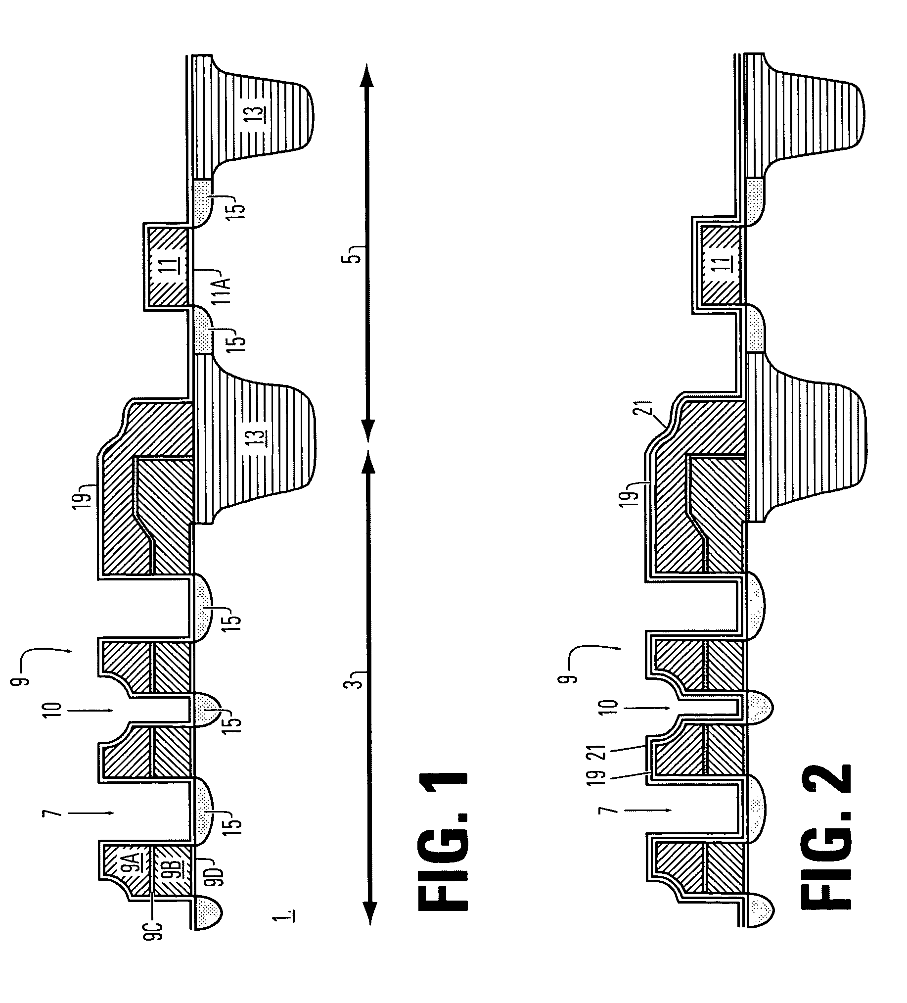
[0020]Reference will now be made in detail to the presently preferred embodiments of the disclosed technology, examples of which are illustrated in the accompanying drawings. Wherever possible, the same or similar reference numbers are used in the drawings and the description to refer to the same or like parts. It should be noted that the drawings are in simplified form and are not to precise scale. In reference to the disclosure herein, for purposes of convenience and clarity only, directional terms, such as, top, bottom, left, right, up, down, over, above, below, and rear are used with respect to the accompany drawings. Such directional terms should not be construed to limit the scope of the invention in any manner.

[0021]Although the disclosure herein refers to certain illustrated embodiments, it is to be understood that these embodiments are presented by way of example and not by way of limitation. The intent of the following detailed description, although discussing exemplary em...


PUM


Abstract

Dual spacer structures are fabricated such that sidewall spacers in a cell region are thinner than sidewall spacers in a periphery region. The fabricating method of memory includes forming a stop layer over the first semiconductor feature and the second semiconductor feature in cell region and periphery region. A spacer layer is formed over the stop layer in the periphery region. The spacer layer is patterned to form a spacer on a sidewall of the second semiconductor feature. An etching process is performed to form a resultant spacer on an interior sidewall of the opening between first semiconductor features. The stop layer on top surfaces of the first and second semiconductor features is removed.

Description

BACKGROUND OF THE INVENTION[0001]1. Field of the Invention[0002]The present invention relates to semiconductor fabrication methods and structures and, more particularly, to a method and structure of fabricating memory device with dual spacers in cell and periphery region.[0003]2. Description of Related Art[0004]Integrated circuits are well known. Integrated circuits are commonly used to make a wide variety of electronic devices, such as memory chips. There is a strong desire to reduce the size of integrated circuits, so as to increase the density of the individual components thereof and consequently enhance the functionality of an integrated circuit. As device densities increase with reduced feature width, the aspect ratio also increases. However, higher aspect ratios resulting from formation of features on a substrate separated by small gaps, can reduce the effective process windows for etching processes and deposition processes. For example, the interlayer dielectric layer gap fil...

Claims


Application Information

Patent Timeline
Patent Type & Authority Patents(United States)
IPC IPC(8): H01L21/336
CPCH01L27/105H01L27/11534H01L27/11526H10B41/40H10B41/43
Inventor HAN, TZUNG TINGCHEN, YIN JENCHEN, MING SHANG
Owner MACRONIX INT CO LTD
Why Eureka
Try Eureka