Long path at-speed testing

a technology of at-speed testing and long path, which is applied in the direction of recording signal processing, instruments, and recording information storage, etc., can solve the problems of the process of identifying functionally exercisable long paths and eliminating false paths can be time, labor and cost intensive, so as to simplify the identification of long paths and reduce chip development costs

Inactive Publication Date: 2006-06-20
BELL SEMICON LLC
View PDF10 Cites 7 Cited by
  • Summary
  • Abstract
  • Description
  • Claims
  • Application Information

AI Technical Summary

Benefits of technology

[0005]The objects, features and advantages of the present invention include providing a method and / or architecture for at-speed testing of integrated circuit chips on a tester that may (i) implement a long test path that is fully controllable, observable, and / or predictable, (ii) have a test delay propagation that is incrementally longer than the longest false path delay (or the longest functional path delay when the functional path is difficult to control and / or observe), (iii) simplify identification of a long path for at-speed testing, (iv) reduce chip development cost and time, (v) identify functionally defective chips, and / or (vi) reduce mis-identification of functionally acceptable chips.

Problems solved by technology

However, the actual longest path in a given design is often difficult to identify due to false paths that the STA tool reports as the longest.
As a result, the process of identifying functionally exercisable long paths and eliminating false paths can be a time, labor, and cost intensive task.

Method used


Image

  • Long path at-speed testing
  • Long path at-speed testing
  • Long path at-speed testing

Examples


Embodiment Construction

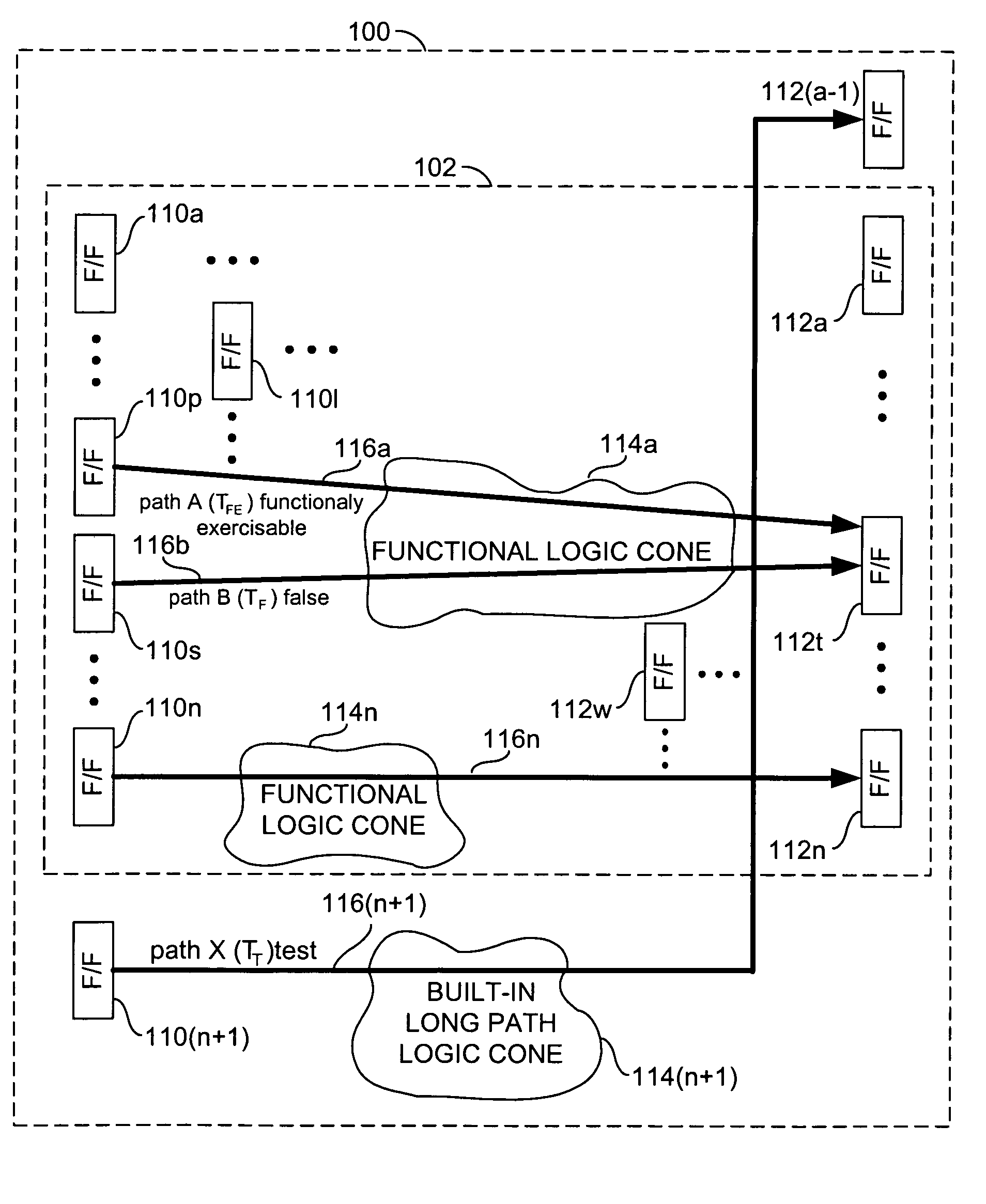
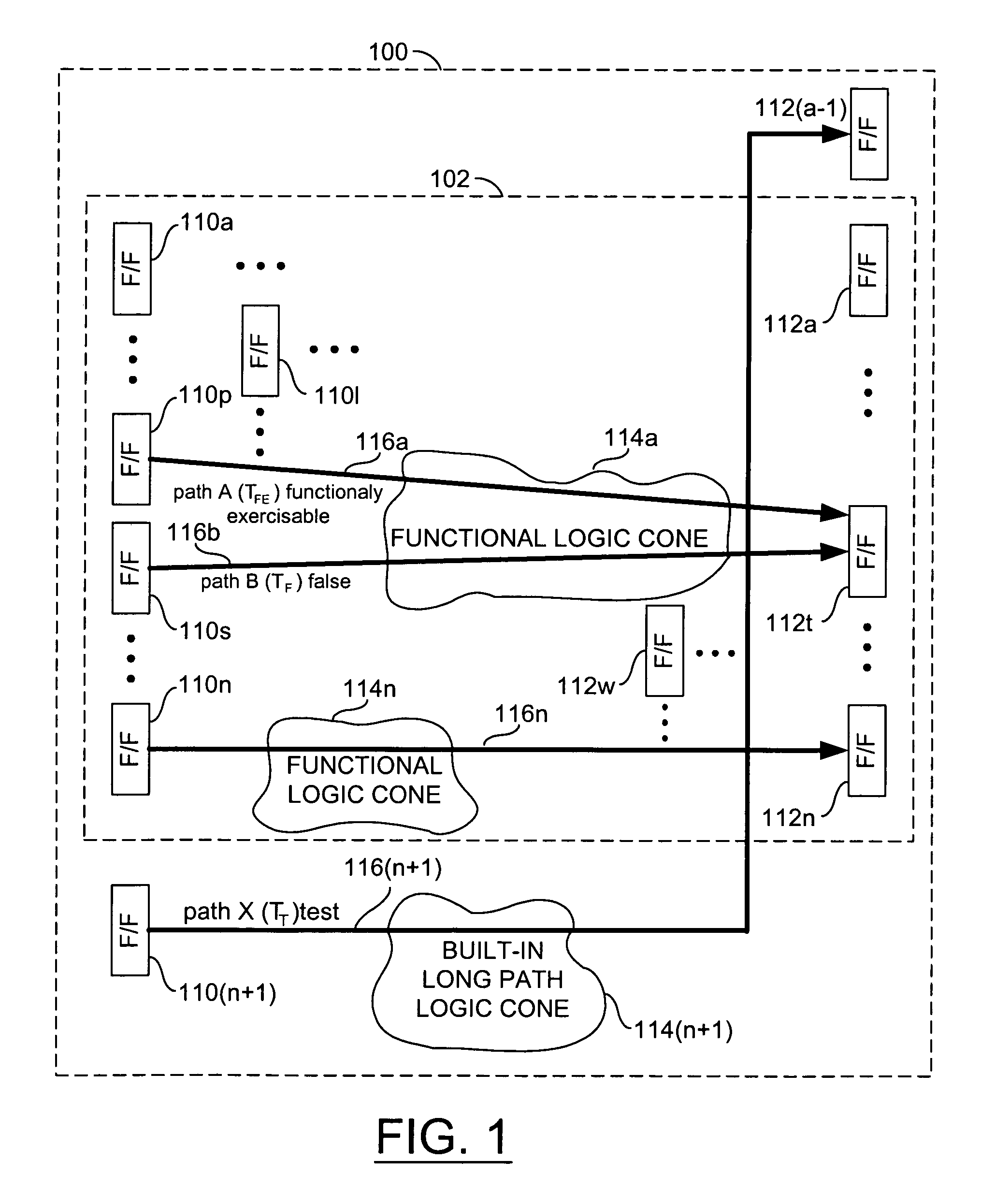
[0011]Referring to FIG. 1, a block diagram illustrating a circuit 100 in accordance with a preferred embodiment of the present invention is shown. The circuit 100 may be implemented as a long path at-speed testing circuit. The circuit 100 may be implemented as an integrated circuit on a semiconductor die (or wafer). The circuit 100 may be exercised by a tester (not shown).

[0012]The circuit 100 generally comprises a base circuit layout 102 and a test circuit. The base circuit layout 102 may comprise a number of base circuits (or devices) 110a–110n, a number of base circuits (or devices) 112a–112n, a number of base circuits (or logic cones) 114a–114n, and a number of base circuit paths 116a–116n. The circuit 100 generally comprises a plurality of the circuits 110, 112, and 114. The circuits 110, 112, and 114 are generally clocked by a common clock. The circuits 110 and 112 are generally implemented as flip-flops (F / Fs). However, any appropriate circuit or device may be implemented acc...


PUM

PropertyMeasurementUnit
time delayaaaaaaaaaa
time delaysaaaaaaaaaa
speedaaaaaaaaaa

Abstract

An apparatus including a plurality of first base circuits, a plurality of second base circuits, a first test circuit, a second test circuit, and a test path. The plurality of first base circuits may be coupled to the plurality of second base circuits via one or more base circuit paths on a layout. The first test circuit may be disposed in a first distal location of the layout. The second test circuit may be disposed in a second distal location of the layout. The test path may be configured to (i) couple the first test circuit to the second test circuit and (ii) generate a test time delay from the first test circuit to the second test circuit incrementally longer than a maximum time delay generated by any of the base circuit paths.

Description

FIELD OF THE INVENTION[0001]The present invention relates to a method and / or architecture for at-speed testing generally and, more particularly, to a method and / or architecture for long path at-speed testing of integrated circuit chips on a tester.BACKGROUND OF THE INVENTION[0002]In order to perform at-speed testing of integrated circuit chips, the longest timing path through the chip must be identified. Electronic Design Automation (EDA) tools are implemented to identify long timing paths within a given design. EDA tools that attempt to identify long timing paths are referred to as Static Timing Analysis (STA) tools. However, the actual longest path in a given design is often difficult to identify due to false paths that the STA tool reports as the longest. A path that is falsely identified as the longest path is typically a path that cannot be exercised functionally on the tester. Once a functionally exercisable long path has been identified, stimulus patterns can be generated. St...

Claims


Application Information

Patent Timeline
Patent Type & Authority Patents(United States)
IPC IPC(8): G11B20/20G06F11/00
CPCG01R31/31725
Inventor SLUITER, DAVID O.MOSS, ROBERT W.KWONG, MARK J.KORGER, PETERGILES, CHRISTOPHER M.
Owner BELL SEMICON LLC
Why Eureka
Try Eureka