
Piston ring and method of manufacturing the same

a technology of piston ring and internal combustion engine, which is applied in the direction of machines/engines, braking systems, transportation and packaging, etc., can solve the problems of increasing wear on the outer peripheral surface affecting the service life of the piston ring, so as to prevent peeling off the film, eliminate problems, and high wear resistance

Inactive Publication Date: 2006-05-30
RIKEN CO LTD
View PDF22 Cites 26 Cited by
  • Summary
  • Abstract
  • Description
  • Claims
  • Application Information

AI Technical Summary

Benefits of technology

[0023](1) The hard ion plating film having high wear resistance which is coated to the outer periphery surface has the compressive residual stress and hence, irrespective of the presence of a frictional force which is repeatedly loaded due to a sliding movement with an inner peripheral wall of a cylinder, it is possible to prevent peeling off the film attributed to fatigue.
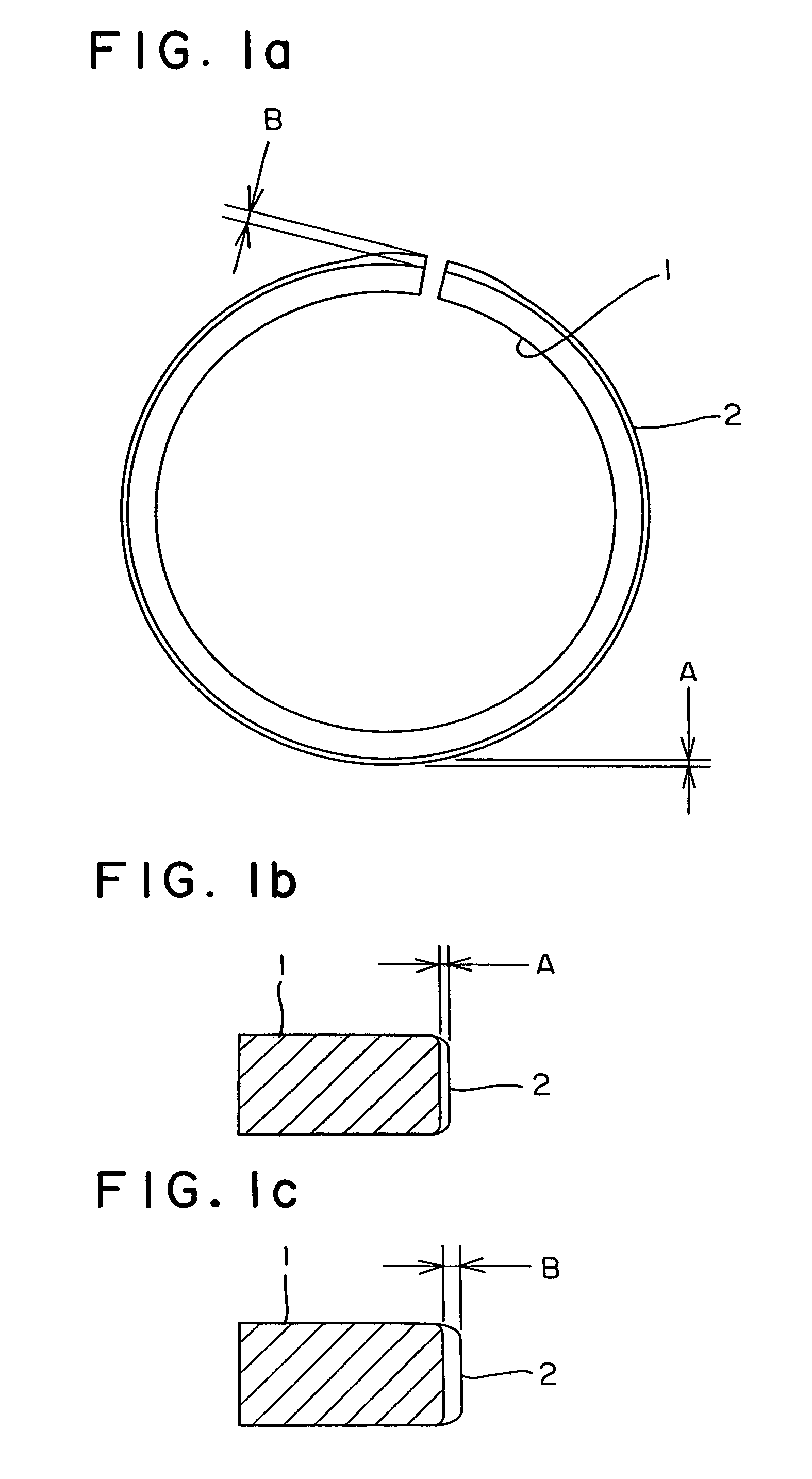
[0024](2) On the outer peripheral surface in the vicinity of the butt ends which is liable to be worn due to the severe sliding condition, the hard film having a large thickness is formed and hence, it is possible to eliminate problems such as lowering of sealing performance or scuffing which are conventionally occurred due to the rapid wear progress by the dissipation of the hard film and the exposure of the substrate material portion.
[0025](3) The hard film has the smaller film thickness at portions other than the butt ends and hence, even when the compressive residual stress is held in the film, chipping of the hard film or the like hardly occurs whereby the yield rate of the manufacturing process can be enhanced. Further, since the film is thin, a tensile residual stress which generates in the substrate portion right below the film is also decreased and hence, the fatigue rupture of the piston ring is hardly occurred.
[0026](4) Compared to a case in which a thick film is uniformly formed on the outer peripheral surface, only a thickness of the portion which is liable to be worn is increased and hence, the film forming time can be shortened whereby the coating productivity using the expensive ion plating equipment can be improved and the target consumption can be also reduced. Accordingly, it is possible to provide the piston ring at a low cost.
[0027](5) Corresponding to an amount of increase of the curvature of the outer peripheral portion of the butt ends which are generated by film forming, it is possible to increase the film thickness in the vicinity of the butt ends compared to that of other portions and hence, in a lapping step, it is possible to easily ensure a contact with the outer peripheral portion of the butt ends of the piston ring whereby the lapping productivity can be enhanced. Alternatively, since the wear of a lapping sleeve can be reduced, it is possible to produce the piston ring at a low cost.
[0028]Next, the advantageous effects of the method for manufacturing the piston ring are explained.

Problems solved by technology

Recently, because of a demand for a higher power of an engine and measures for an exhaust gas to minimize atmospheric pollution, use environment of the piston ring is becoming severer and wear of an outer peripheral surface of the piston ring has been a problem to be solved.
However, in a diesel engine using a piston ring with such a nitride on an outer peripheral surface thereof as a hard film, when the combustion pressure is high or when an exhaust gas countermeasure is taken by a large quantity of EGR (Exhaust Gas Recirculation), there arises the problem that the wear on the outer peripheral slide surface is increased.
Accordingly, it is less than optimal to ensure the lifetime and the sealing performance of the piston ring for a long time.
Particularly, with respect to an outer peripheral slide surface of a portion of butt ends of a top ring which define a gap, since a high temperature combustion gas passes a closed gap between the butt ends when compressed within a cylinder and hence, the lubrication condition is more serious compared to other portions.
Due to such wear, when the hard film formed on the outer peripheral slide surface of the butt ends or the portion thereof by ion plating is dissipated, a steel material which constitutes a substrate is exposed to a slide surface so that the wear rapidly progresses whereby the closed gap size between the butt ends is increased resulting in lowering of the sealing function.
Further, a lubricating oil leaks to a combustion chamber side and this brings about not only the increase of an oil consumption but also the occurrence of environmental problem such as the increase of sulfuric component in an exhaust gas or the like.
Further, when the hard film is dissipated due to wear and the substrate material of steel is exposed, the danger of engine scuffing is also increased.
Accordingly, it is the fact that the proposal disclosed in the previously mentioned publication is also less than optimal as the countermeasure.
Further, in a high-load diesel engine which increases the combustion pressure or in an engine which adopts an exhaust brake, the piston ring is deformed in a dish shape at the time of explosive combustion or at the time of operating an exhaust brake and this is liable to induce wear of ring grooves of the piston.
Due to this repeated deformation stress, the fatigue breakage of the piston ring is liable to be induced at a position opposite to the butt ends at which the stress is concentrated.
The hard film is poor in toughness and cracks are liable to easily initiate due to the stress concentration.
Further, when the hard film is made of nitride formed by ion plating (for example, chromium nitride, titanium nitride or nitrides in which oxygen, carbon, boron or the like is added to those nitrides), there has been a problem that the film is peeled off due to fatigue of repeated friction force which is attributed to the sliding movement between the piston ring and an inner peripheral wall of the cylinder.
When a defect or the like exists in the vicinity of the portion, it functions as a starting point of fatigue failure and hence, there arises a new problem that the breakage of the piston ring is liable to occur easily.
Further, when the hard film is uniformly thick as mentioned previously, there arises a problem on a cost besides the above-mentioned problems.
Particularly, when the hard film is formed by ion plating, ion plating equipment is expensive, the film forming speed is slow compared to that of other method such as electric plating or thermal spraying and hence, the productivity is low.
Further, a target such as chromium or titanium is also expensive, the greater the film thickness, the piston ring becomes more costly.
However, as mentioned previously, when the compressive stress remains in the film, the film is deformed even at a temperature which the microstructure change of the material does not occur and this deformation is remarkably large when the heat-resistant element in the substrate material is small in quantity.
To obtain the complete contact between the outer peripheral portion of the piston ring and the inner peripheral wall of the lapping sleeve, it takes a considerable time for lapping and, in a worst case, even when the other film is dissipated, the contact in the vicinity of the butt ends cannot be obtained.
Further, since an inner peripheral surface of the sleeve for lapping is worn out in that case, the lifetime of the sleeve for lapping is extremely shortened resulting in the manufacturing of costly piston ring.

Method used


Image

  • Piston ring and method of manufacturing the same
  • Piston ring and method of manufacturing the same
  • Piston ring and method of manufacturing the same

Examples


Embodiment Construction

[0037]Hereinafter, embodiments of the present invention are explained in detail.

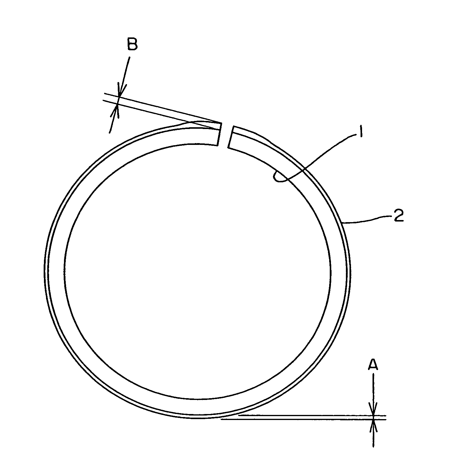
[0038]FIG. 1 shows a piston ring 1 which constitutes one example of the present invention. In the drawing, (a) is a plan view of the piston ring as viewed in the axial direction and (b) is a cross-sectional view of the piston ring 1 in the radial direction of a portion opposite to butt ends, wherein A indicates a thickness of an ion plating film 2. (c) is a cross-sectional view of the piston ring 1 in the radial direction in the vicinity of the butt ends, wherein B indicates a thickness of the ion plating film 2.

[0039]A typical manufacturing process of the above-mentioned piston ring is explained.

[0040]First of all, a steel wire or strip material capable of having arbitrary various cross-sectional shapes is formed into a coil of an approximately piston ring shape. Here, an outer peripheral surface shape may be also a BF (Barrel Faced), an eccentric BF or a half BF.

[0041]In coiling step, the steel wire ma...


PUM

PropertyMeasurementUnit
thicknessaaaaaaaaaa
temperatureaaaaaaaaaa

Abstract

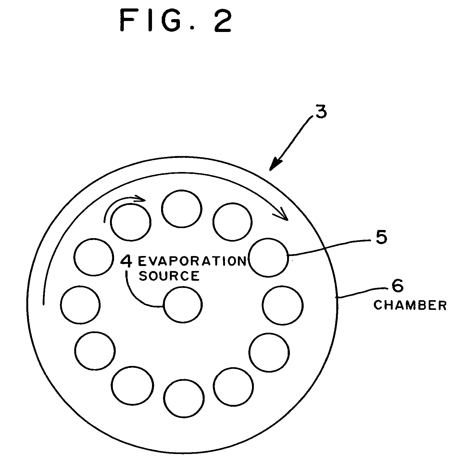
A manufacturing method of a piston ring is developed, wherein the method provides a countermeasure for wear of butt ends of the ion plating film coated piston ring and a countermeasure for breakage of the piston ring and the piston ring manufactured at a low cost. A thickness of the film (2) in the vicinity of butt ends (7) of a piston ring (1) is made greater than the thickness of the film (2) at other outer peripheral surface. Piston ring blanks (5) are rotated around their own axes toward an evaporation source (4) and a speed is lowered when the butt ends (7) face the evaporation source (4).

Description

TECHNICAL FIELD[0001]The present invention relates to a piston ring for an internal combustion engine, and more particularly to a piston ring for an internal combustion engine which exhibits an improvement on a film and a thickness of an outer peripheral surface thereof and a method for manufacturing the same.BACKGROUND ART[0002]Recently, because of a demand for a higher power of an engine and measures for an exhaust gas to minimize atmospheric pollution, use environment of the piston ring is becoming severer and wear of an outer peripheral surface of the piston ring has been a problem to be solved. To cope with such the problem, there has been provided a piston ring which has an outer peripheral surface thereof coated with a hard film which exhibits excellent anti-scuffing and wear resistance such as a film made of chromium nitride, titanium nitride or the like by ion plating in place of a conventional hard chromium plating film or nitriding treatment.[0003]However, in a diesel eng...

Claims


Application Information

Patent Timeline
Patent Type & Authority Patents(United States)
IPC IPC(8): F16J9/26F02F5/00C23C14/32C23C14/50C23C14/54F16J9/14
CPCC23C14/505F16J9/26F16J9/14C23C14/542F02F5/00
Inventor MIIDA, HIROSHI
Owner RIKEN CO LTD
Learn More