
Pumping light source for laser-active media

Inactive Publication Date: 2006-05-23
TRUMPF LASER GMBH CO KG
View PDF16 Cites 0 Cited by
  • Summary
  • Abstract
  • Description
  • Claims
  • Application Information

AI Technical Summary

Benefits of technology

[0006]The advantage of the inventive solution is to be seen in the fact that the formation of a diffuse gas discharge, which, for its part, reduces the sputtering and vaporization of electrode material and, in addition, also favors the thermal stressing of the outer member on account of more favorable flow ratios during the diffuse gas discharge, is promoted by the radiation cooling.
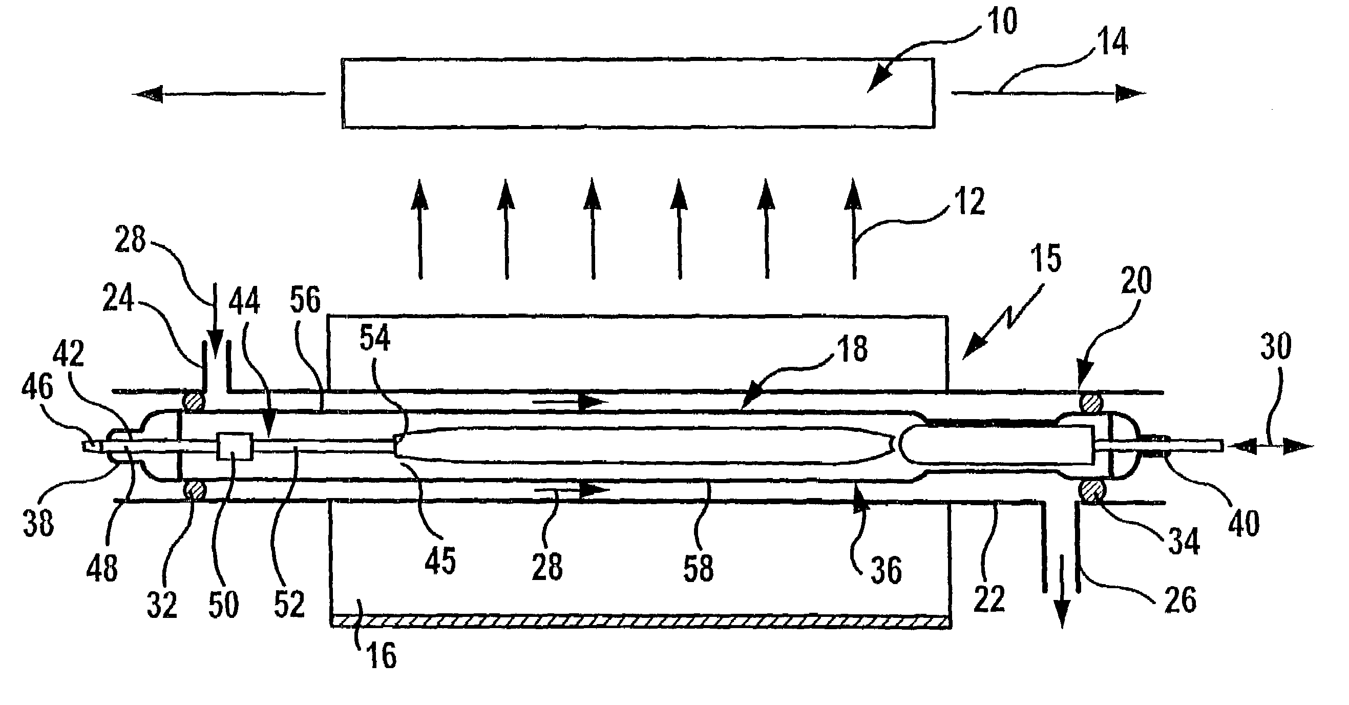
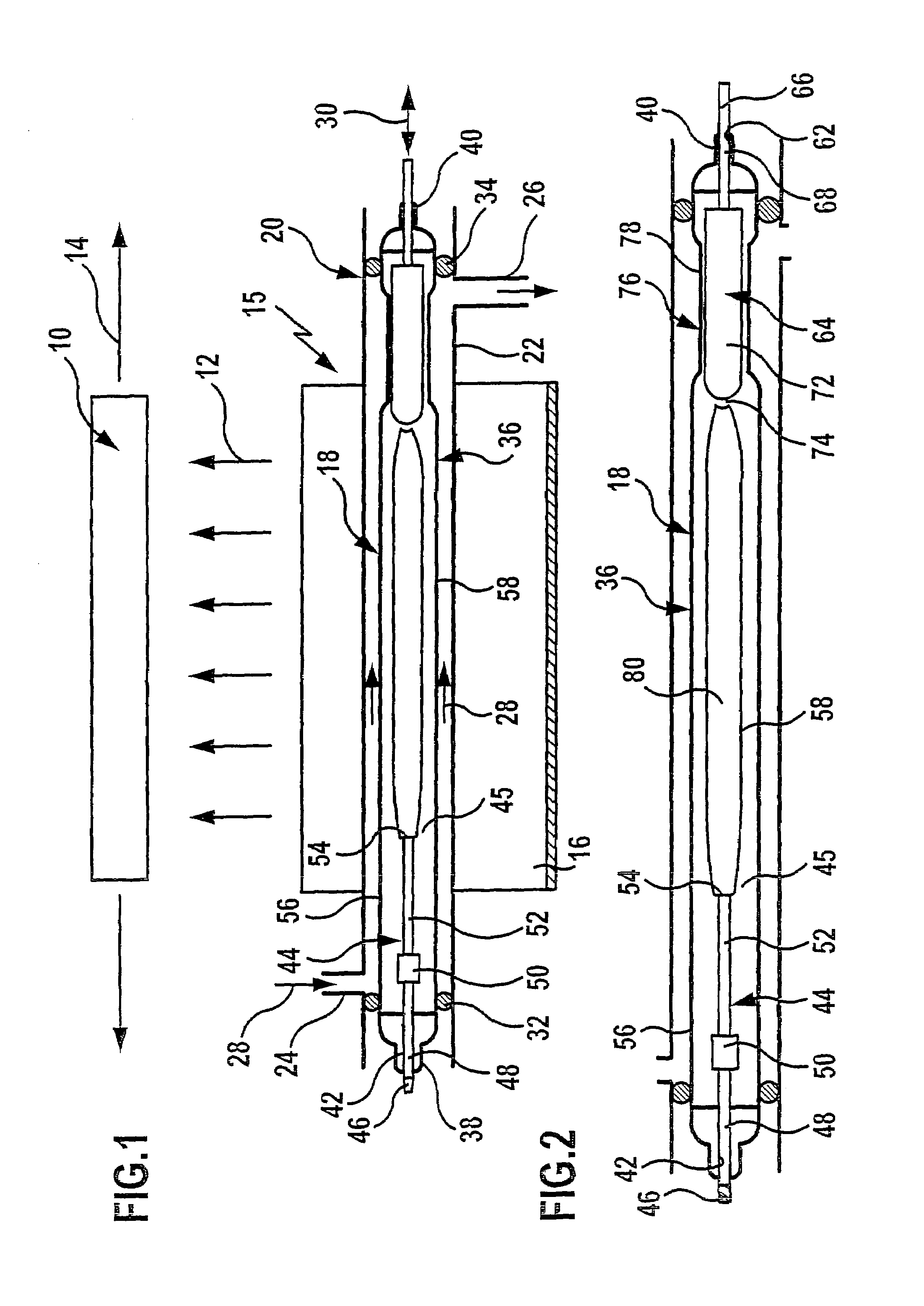
[0034]With respect to the start of the gas discharge, no further details have so far been given. One particularly advantageous embodiment provides for a surface discontinuity to be provided at the first electrode end for forming a gas discharge starting in a punctiform manner at this discontinuity. As a result, the start of the gas discharge and, therefore, the triggering of the pumping light source are facilitated and, in particular, a start of the gas discharge at a defined point of the electrode end can be achieved as a result and so the starting conditions may be optimized.

Problems solved by technology

Pumping light sources for laser-active media of this type are known from the state of the art, wherein the problem always exists that the service life of such pumping light sources is limited, namely, in particular, due to several effects which are connected to one another.
These effects are vaporization or sputtering of electrode material which is deposited, in particular, on the outer member and leads to thermal stressing thereof and, in addition, stressing of the outer member due to unfavorable gas discharge procedures.

Method used


Image

  • Pumping light source for laser-active media
  • Pumping light source for laser-active media
  • Pumping light source for laser-active media

Examples


second embodiment

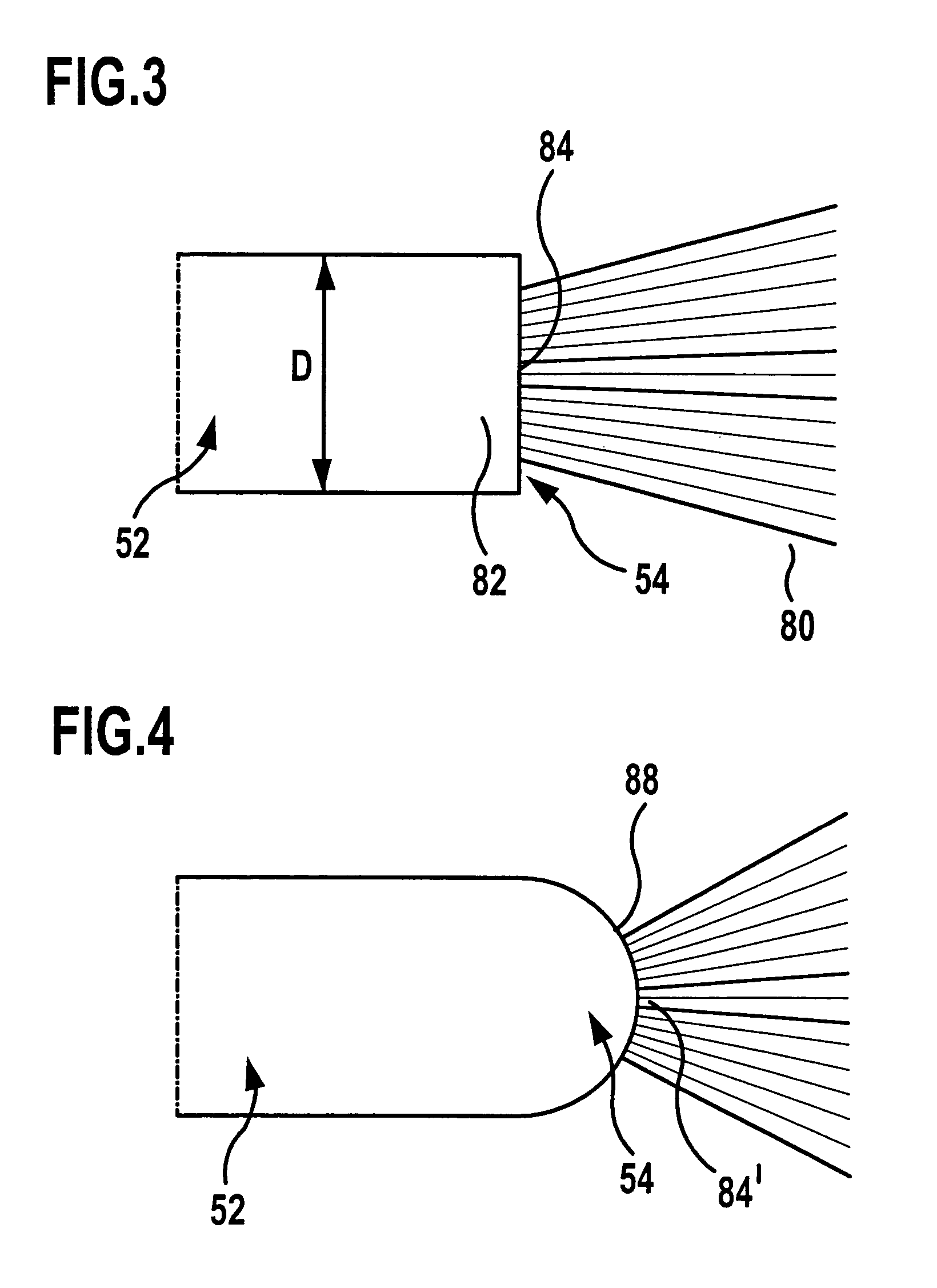
[0067]However, it is also conceivable, as illustrated in FIG. 4 in a second embodiment, to provide as surface area 84′ a section from an optional mathematical surface 88, for example, a spherical cap which extends in a continuous manner, wherein it is ensured due to the continuous extension that, likewise, no corners, edges or points occur in the surface area 84′ which would give the gas discharge 80 the possibility of transferring from the diffuse mode into the spot mode.

[0068]In order to keep the cooling of the volume area 82 by way of heat conduction as slight as possible, it is preferably provided for the heat resistance in the first electrode 44 between the first hot electrode end 54 and the cooled electrode opening 42 to be at least 10° C. / W, even better to be greater. This may be realized particularly favorably in that the average cross section of the first electrode 44 between the first electrode end 54 and the electrode opening 42 is smaller than one tenth of the distance b...

third embodiment

[0075]In order to ensure a permanent connection between the front end section 52 and the holding section 48, the connection 50 in a third embodiment illustrated in FIG. 5 is preferably formed by a sleeve 90 which is provided with two bores, namely a bore 92 for an end 96 of the holding section 48 and a bore 94 for an end 98 of the front end section 52, into which these engage and are, therefore, already connected in a form-locking manner. In addition, a joining connection by way of soldering or welding is preferably produced.

fourth embodiment

[0076]Alternatively thereto, it is, however, also conceivable, as illustrated in FIG. 6 for a fourth embodiment, to provide the connection 50′ between the holding section 48 and the front end section 52 in the form of a welding of the ends 96 and 98 abutting on one another.


PUM


Abstract

In order to improve a pumping light source for laser-active media comprising an outer member enclosing a gas discharge medium, a first electrode acting as a cathode and having a first electrode end located within the outer member, a second electrode acting as an anode and having a second electrode end located within the outer member and a gas discharge chamber located within the outer member between the electrode ends facing one another, in such a manner that the service life thereof is longer it is suggested that the first electrode end be essentially cooled by radiation and that a predominantly diffuse gas discharge be formed proceeding from an areally extended surface area located at the first electrode end.

Description

[0001]This application is a continuation of commonly assigned U.S. patent application Ser. No. 10 / 118,594 filed on Apr. 8, 2002, now abandoned which application claims priority of German patent application no. 102 08 585.4 filed on Feb. 22, 2002.BACKGROUND OF THE INVENTION[0002]The invention relates to a pumping light source for laser-active media, comprising an outer member enclosing a gas discharge medium, a first electrode acting as a cathode and having a first electrode end located within the outer member, a second electrode acting as an anode and having a second electrode end located within the outer member and a gas discharge chamber located within the outer member between the electrode ends facing one another.[0003]Pumping light sources for laser-active media of this type are known from the state of the art, wherein the problem always exists that the service life of such pumping light sources is limited, namely, in particular, due to several effects which are connected to one...

Claims


Application Information

Patent Timeline
IPC IPC(8): H01S3/22H01J61/80H01S3/092
CPCH01J61/0735H01J61/80H01S3/092H01J61/90H01S3/04
Inventor IFFLAENDER, REINHARD
Owner TRUMPF LASER GMBH CO KG
Learn More