Eureka AIR delivers breakthrough ideas for toughest innovation challenges, trusted by R&D personnel around the world.

Surface acoustic wave hydrogen sensor

a surface acoustic wave and hydrogen sensor technology, applied in the field of surface acoustic wave hydrogen sensor, can solve the problems of high power requirements, high operating temperature, and the rise of the storage of this gas

Inactive Publication Date: 2006-05-23
UNIV OF SOUTH FLORIDA
View PDF2 Cites 46 Cited by
  • Summary
  • Abstract
  • Description
  • Claims
  • Application Information

AI Technical Summary

Benefits of technology

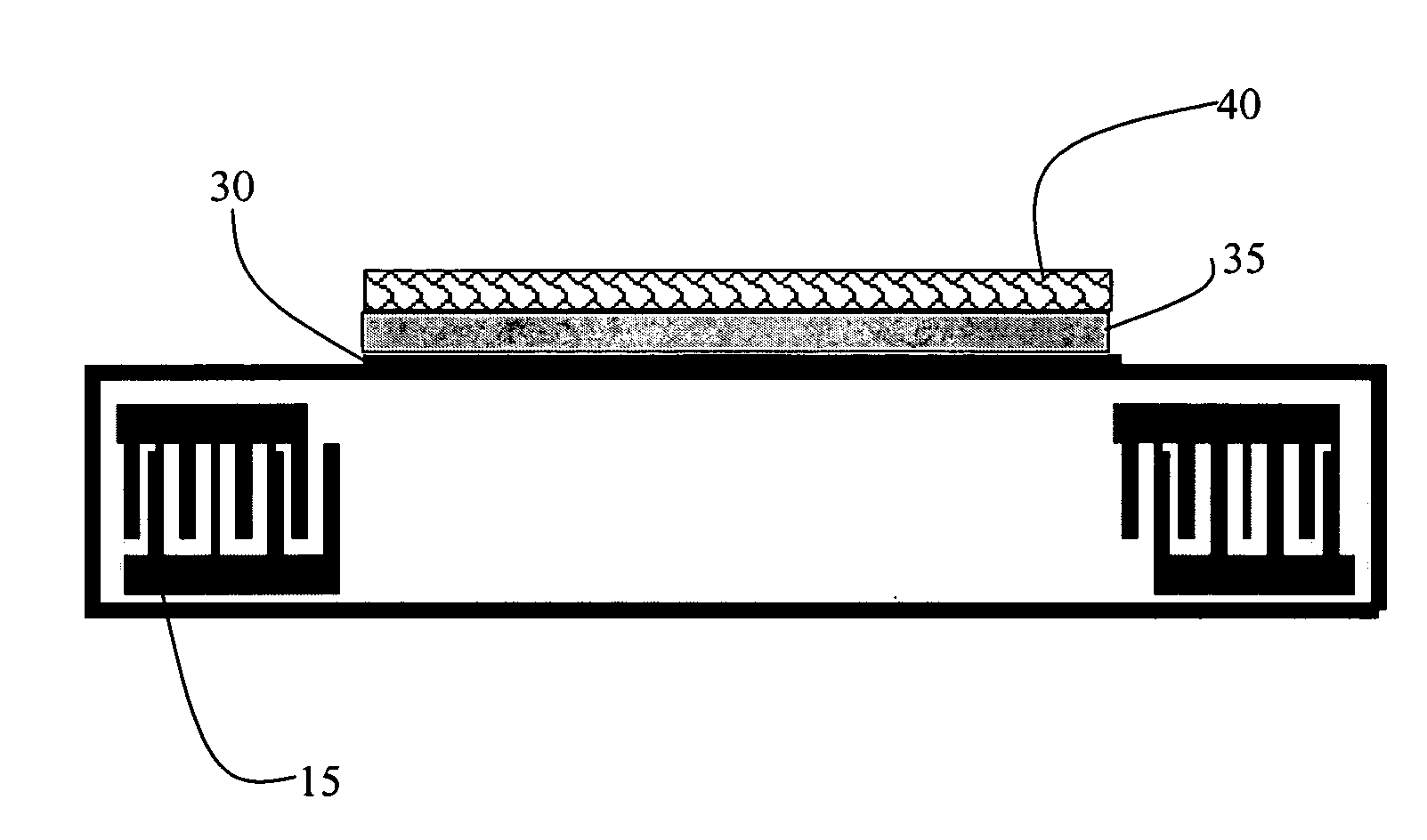
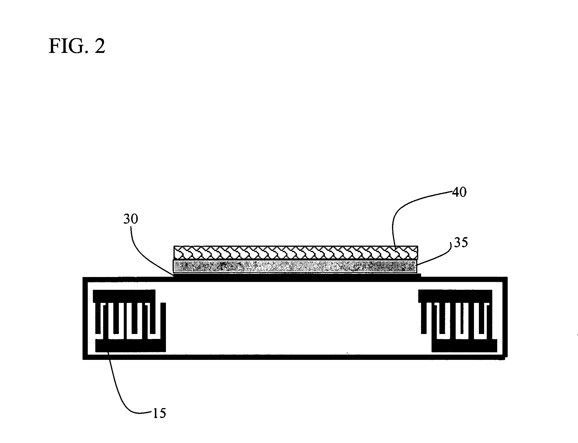
[0016]The sensing bilayer in accordance with the present invention comprising two or more layers that takes advantage of the mass, modulus and / or electro-acoustic perturbation mechanisms of the SAW sensor The sensing bilayer in accordance with the present invention may additionally comprise a nanocrystalline or other nanomaterial such as nanoparticles or nanowires of metal and / or alloy selected from nickel, palladium, platinum or silver, with palladium being a most preferred single metal species. The foregoing metal species may be utilized in combination with one another in the form of alloys or blends of two or more of such metals, or a metal of such type may be used in combination in an alloy blend or composite, with other materials. As an example, a Pd / Ni alloy would be effective in the present invention and also provide mechanical stability against the expansion caused by hydrogen absorption.
[0018]In employment of the device as a hydrogen sensor, the surface acoustic wave device and accompanying sensing layer is positioned with an environment. An input voltage applied to the surface acoustic wave device results in the surface acoustic wave device exhibiting a frequency response. Accordingly, the sensing bilayer interacts and reversibly changes the frequency response of the surface acoustic device upon exposure to hydrogen gas in the environment and a sensor output is provided for outputting the change in the frequency response of the surface acoustic device. As a result, the sensor is effective in the detection of hydrogen gas at a concentration of from 0% to at least 30%. Preferably, the hydrogen sensor is sensitive to hydrogen at a concentration of 0.05%. The hydrogen gas sensor in accordance with the present invention is sensitive to hydrogen in air and in inert atmospheres.

Problems solved by technology

In fact, a number of problems arise involving the storage of this gas.
These devices suffer from high operating temperatures, high power requirements and slow response times. Doped metal oxides, typically SnO2, for use as hydrogen sensors are known in the art.
While these devices are capable of low level detection, they suffer from high power consumption, slow response times, and are not thermally stable at the high operating temperatures required.
However, the palladium nanowire array devices available to date require a predetermined nanowire array structure and do not exhibit the desired low level detection for a hydrogen sensor.
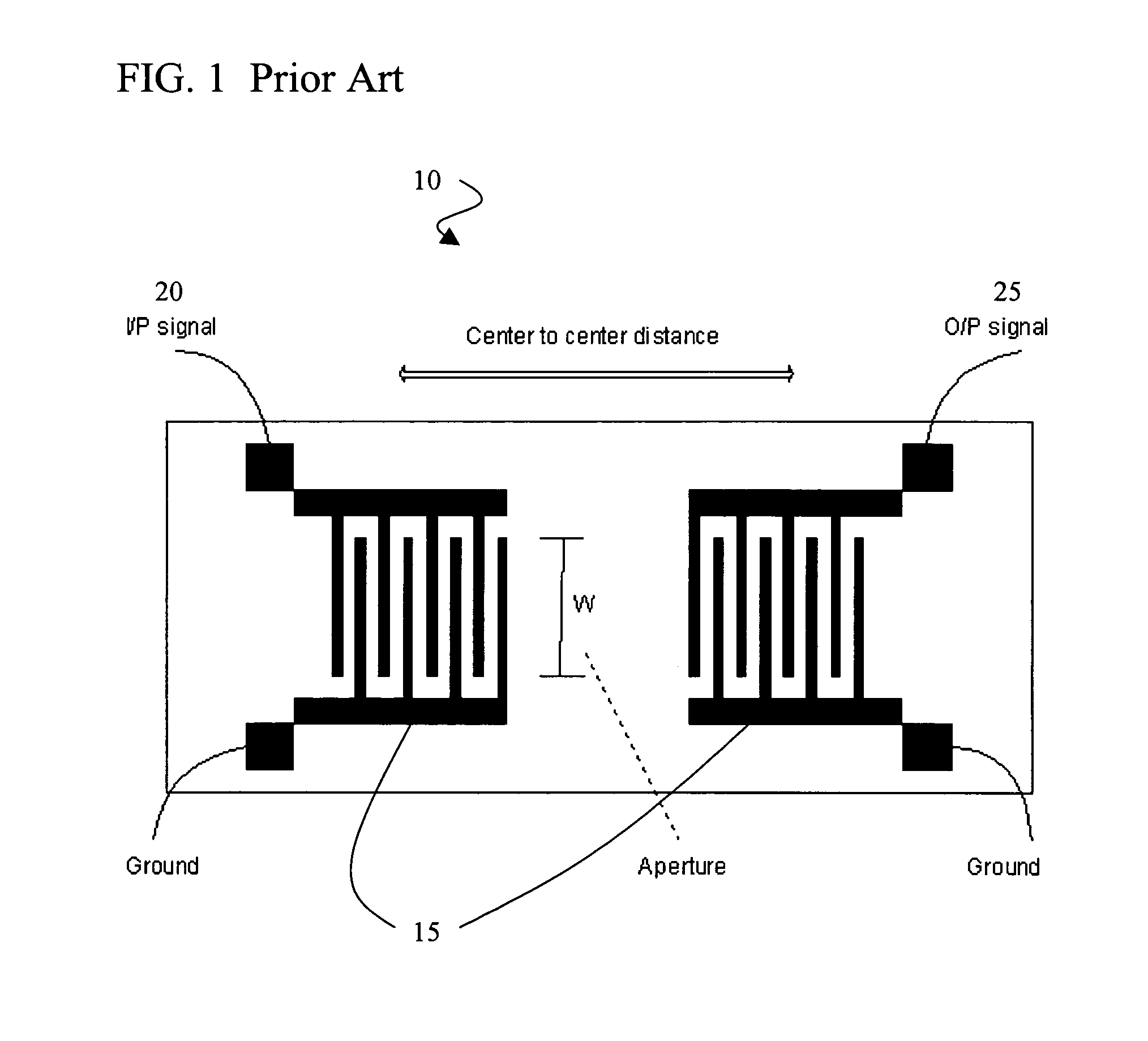
As a result of this relationship, physical limitations exist at higher frequencies when the electrodes become too narrow to fabricate with standard photolithographic techniques and at lower frequencies when the devices become impractically large.

Method used


Image

  • Surface acoustic wave hydrogen sensor
  • Surface acoustic wave hydrogen sensor
  • Surface acoustic wave hydrogen sensor

Examples


example

[0046]The table of FIG. 4 provides the independent parameters for the SAW device of this exemplary embodiment.

[0047]The complete characterization of an acoustic wave device is always obtained from a complete frequency response spectrum including all the scattering parameters. Scattering parameters (S-parameters) are the set of parameters describing the scattering and reflection of traveling waves when a network is inserted into a transmission line. S-parameters are normally used to characterize high frequency networks, where simple models valid at lower frequencies cannot be applied. S-parameters are normally measured as a function of frequency.

[0048]For each port, the incident (applied) and reflected wave properties are measured. When the incident wave travels through the network, its value is multiplied (i.e. its gain and phase are changed) by scattering, thus giving the resulting output value. S-parameters can be considered as the gain of the network, and the subscripts denote th...


PUM


Abstract

The present invention provides a delay line SAW device fabricated on a lithium niobate substrate and coated with a bilayer of nanocrystalline or other nanomaterials such as nanoparticles or nanowires of palladiumn and metal free pthalocyanine which will respond to hydrogen gas in near real time, at low (room) temperature, without being affected by CO, O2, CH4 and other gases, in air ambient or controlled ambient, providing sensitivity to low ppm levels.

Description

CROSS REFERENCE TO RELATED APPLICATIONS[0001]This application claims priority to U.S. Provisional Patent Application No. 60 / 481,063, entitled, “Nano-Wire and Nano-Particle Based SAW and QCM Sensor”, filed Jul. 7, 2003.STATEMENT OF GOVERNMENT INTEREST[0002]This invention was made with Government support under Grant No. 2106353 awarded by NASA / FSEC. The Government has certain rights in the invention.BACKGROUND OF INVENTION[0003]Hydrogen gas is used in the process of manufacturing semiconductors, and has gained popularity as a clean source of energy or as a fuel gas. However, the increasing use of hydrogen gas should not be considered as one without disadvantages. In fact, a number of problems arise involving the storage of this gas. A hydrogen leak in large quantities should be avoided because hydrogen, when mixed with air in the ratio of approximately 4.65:93.9 volume % is explosive. Hence, it is important to develop highly sensitive hydrogen detectors to prevent accidents due to its...

Claims


Application Information

Patent Timeline
IPC IPC(8): G01N29/00
CPCG01N29/022G01N29/036G01N29/30G01N29/326G01N2291/0212G01N2291/0426G01N2291/0256G01N2291/02881G01N2291/0422G01N2291/0423G01N2291/0255
Inventor BHETHANABOTLA, VENKAT R.BHANSALI, SHEKHAR
Owner UNIV OF SOUTH FLORIDA
Why Eureka
Eureka Blog
Learn More