
Cache system and method for controlling the cache system comprising direct-mapped cache and fully-associative buffer

a cache system and cache technology, applied in the direction of memory adressing/allocation/relocation, instruments, climate sustainability, etc., can solve the problems of significant delay, significant impact on execution speed and power consumption of a cpu, and the time of accessing a memory upon the request of a cpu, so as to reduce the rate of misses and power consumption

Inactive Publication Date: 2006-05-16
SAMSUNG ELECTRONICS CO LTD +2
View PDF3 Cites 26 Cited by
  • Summary
  • Abstract
  • Description
  • Claims
  • Application Information

AI Technical Summary

Benefits of technology

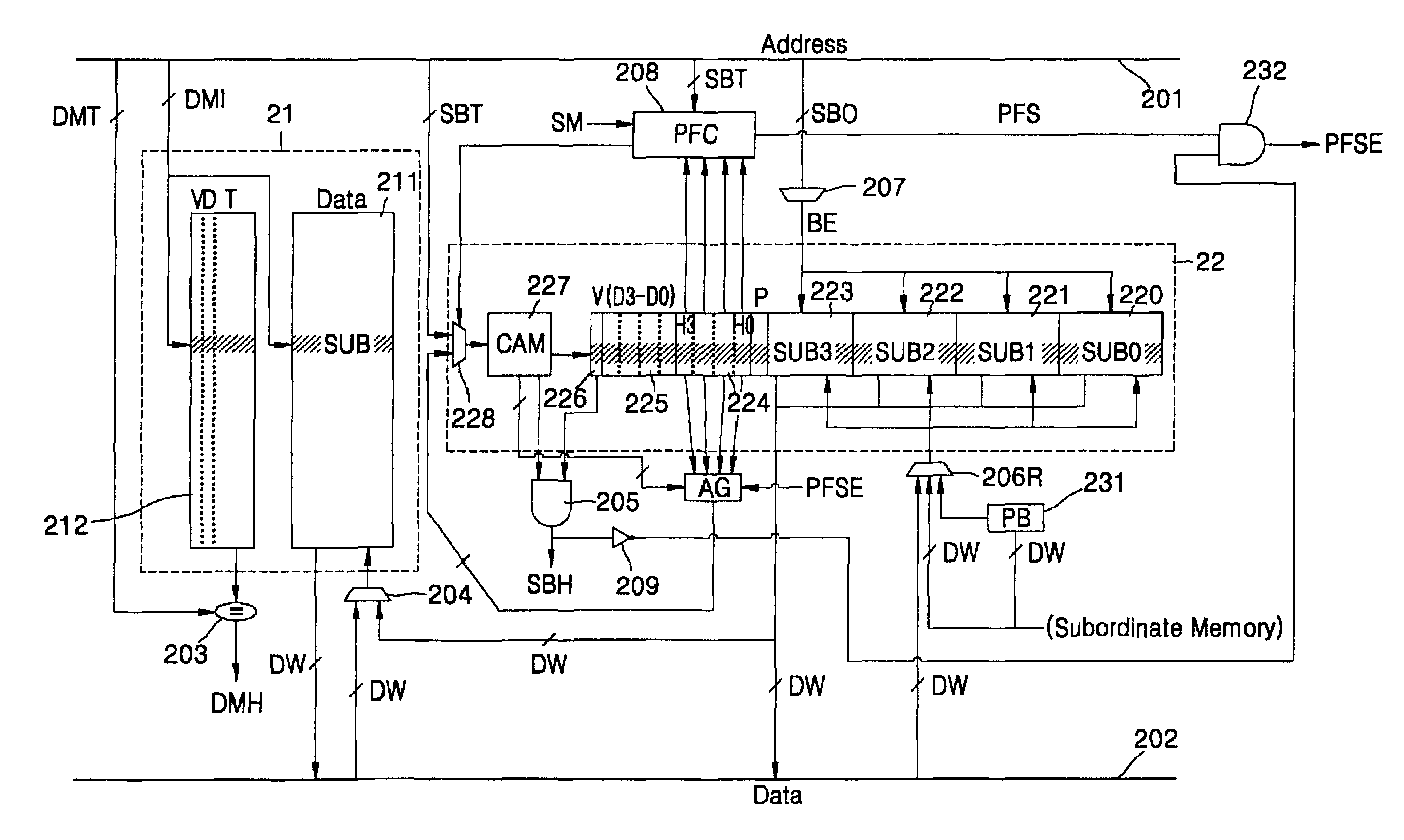
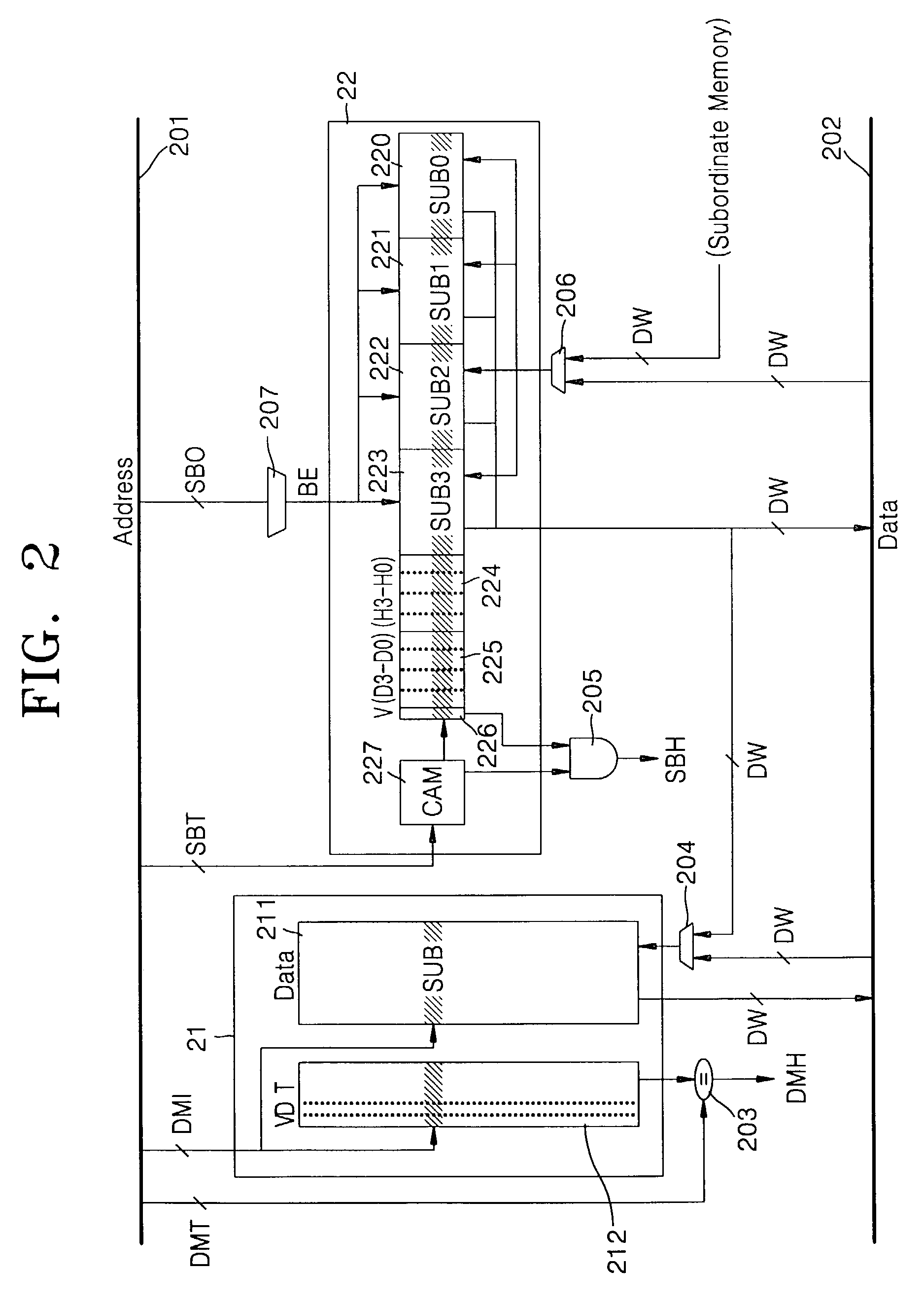
[0007]The present invention is directed to a cache system that includes two caches with different configurations and its control method to exploit temporal locality and spatial locality, resulting in reduced miss ratio and power consumption.
[0015]When a miss occurs in both the direct-mapped and the fully associative spatial buffer, data of missed addresses and nearby addresses is fetched into a large block of the spatial buffer. If a reference misses in the direct-mapped cache, but hits in the spatial buffer, its corresponding small block is fetched from the spatial buffer and its hit bit is set. Using this hit bit enables the cache system to selectively determine those blocks showing temporal locality. Thus, data may reside in the direct-mapped cache for a long period, and therefore the temporal locality is raised, which results in reducing miss rates and power consumption.

Problems solved by technology

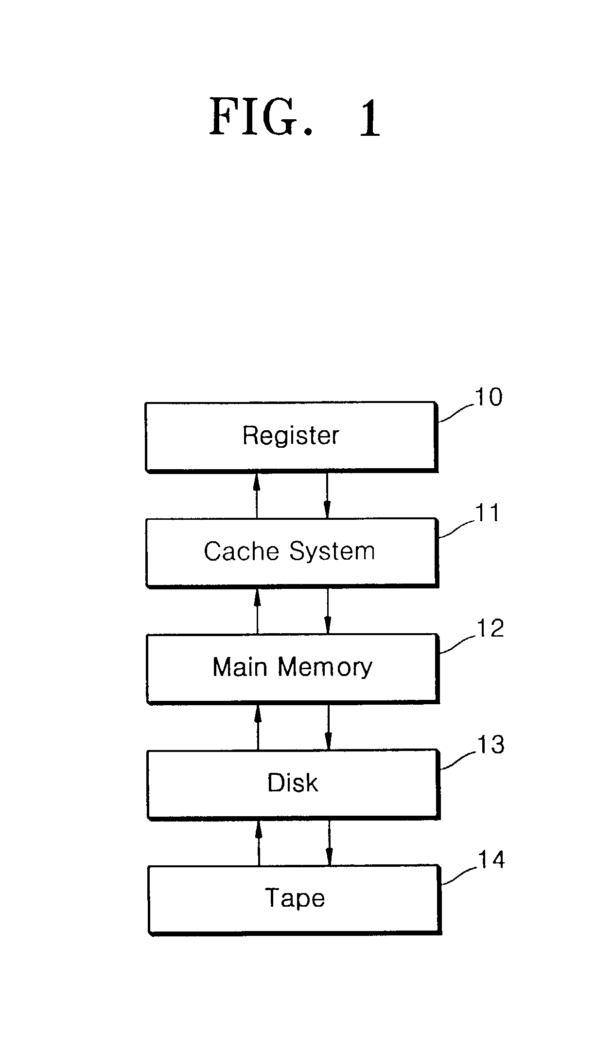
In present day multilevel and complex memory systems, access time to a memory upon the request by a CPU for instructions or data can engender considerable delays.
Among the above memories, the cache system 11 is accessed prior to the main memory 12, and therefore the structure and controlling method of the cache system may significantly impact the execution speed and power consumption of a CPU.
These conventional cache control methods have problems in that they are complex in design and have high hardware cost.

Method used


Image

  • Cache system and method for controlling the cache system comprising direct-mapped cache and fully-associative buffer
  • Cache system and method for controlling the cache system comprising direct-mapped cache and fully-associative buffer
  • Cache system and method for controlling the cache system comprising direct-mapped cache and fully-associative buffer

Examples


Embodiment Construction

[0023]According to an embodiment of the present invention, a cache system, to which a cache control method is applied, includes a direct-mapped cache 21 and a fully associative spatial buffer 22, as shown in FIG. 2. The direct-mapped cache 21 includes a data storage unit 211 and a control bit storage unit 212. The data storage unit 211 is configured such that data accessed by a central processing unit (CPU, not shown) are stored in an 8-byte small block (SUB). The control bit storage unit 212 stores a group of bits, i.e., a 1-bit valid bit (V), a 1-bit dirty bit (D), and an n-bit tag bit (T), for each small block (SUB) in response to an index signal DMI input through an address bus 201. A comparator 203 checks to see if a value of a tag signal DMT input from the CPU through the address bus 201 exists in the tag bit (T) of the control bit storage unit 212, and generates an access result signal DMH indicative of whether access to the direct-mapped cache 21 is a hit or miss. The access...


PUM


Abstract

A method is provided for controlling a cache system. The cache system to be controlled comprises a direct-mapped cache configured with a small block size, and a fully associative spatial buffer configured with a large block, which includes a plurality of small blocks. Where accesses to the direct-mapped cache and the fully associative buffer are misses, data of a missed address and data of adjacent addresses are copied to the large block in the fully associative spatial buffer according to a first-in-first-out (FIFO) process. Furthermore, if one or more small data blocks is accessed among its corresponding large block of data which is to be expelled from the fully associative buffer, the small block(s) accessed is copied to the direct-mapped cache.

Description

FIELD OF THE INVENTION[0001]The present invention relates to a method for controlling a cache system to improve an access speed of a central processing unit (CPU), and more particularly, to a method for controlling a cache system having a direct-mapped cache and a fully associative buffer.BACKGROUND[0002]In present day multilevel and complex memory systems, access time to a memory upon the request by a CPU for instructions or data can engender considerable delays. A memory hierarchy is needed which is arranged according to the order in which the CPU accesses data from different memories in the hierarchy, as shown in FIG. 1. Referring to FIG. 1, the CPU accesses memories in the order of a register 10, a cache system 11, a main memory 12, a disk 13, and a tape 14. Here, the register 10 having the fastest access time is referred to as the highest hierarchical level and the tape 14 having the slowest access time is referred to as the lowest hierarchical level.[0003]Among the above memor...

Claims


Application Information

Patent Timeline
Patent Type & Authority Patents(United States)
IPC IPC(8): G06F12/00G06F12/02G06F12/08G06F12/12
CPCG06F12/0897G06F12/0864Y02B60/1225Y02D10/00G06F12/02
Inventor KIM, SHIN-DUGLEE, JUNG-HOON
Owner SAMSUNG ELECTRONICS CO LTD
Learn More