
System and method for closed-loop control of laser cladding by powder injection

a laser cladding and closed-loop control technology, applied in process and machine control, process control, electric programme control, etc., can solve the problems of poor reproducibility, poor quality cladding, and limited use of vision systems based on ccd technology in closed-loop control systems. , to achieve the effect of improving controller performance, high precision and accurate measurement of cladding geometry

Active Publication Date: 2006-05-09
TOYSERKANI EHSAN +2
View PDF9 Cites 74 Cited by
  • Summary
  • Abstract
  • Description
  • Claims
  • Application Information

AI Technical Summary

Benefits of technology

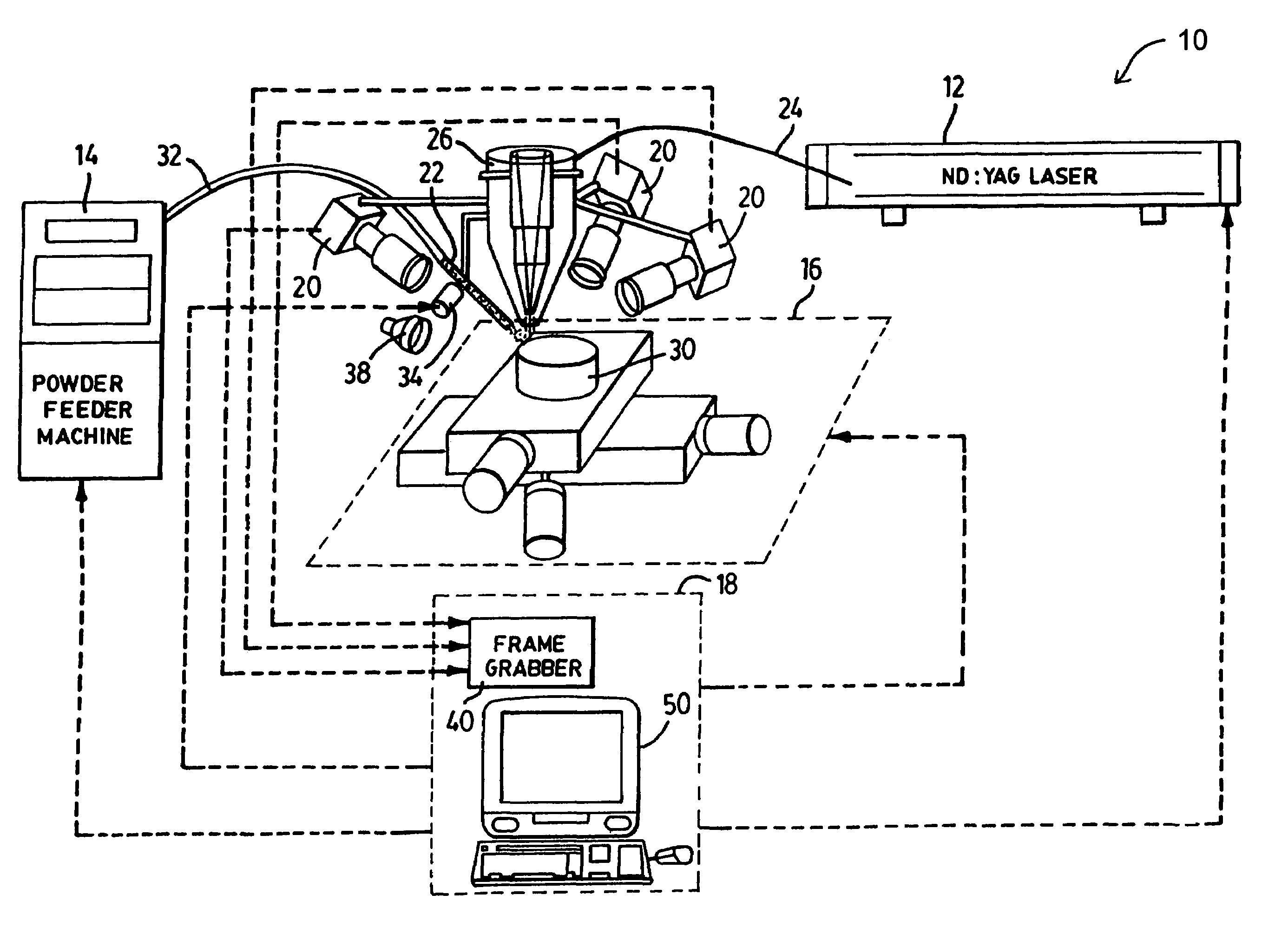
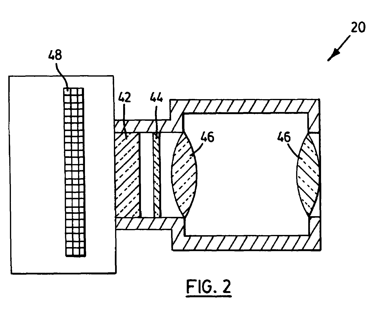
[0090]In summary, the present invention provides several advantages, namely it provides a system for automatically controlling the laser cladding process and provides a closed-loop control strategy for adjusting the laser power, powder feedrate, and process speed. In one embodiment the invention provides an optical CCD-based detector for obtaining live pictures of the process zone. The control system provides pattern recognition methodology to determine clad dimensions and rate of solidification from the images provided by the opt

Problems solved by technology

This poor reproducibility arises from the high sensitivity of laser cladding to small changes in the operating parameters such as laser power, beam velocity and powder feed rate, as well as to process disturbances such as variations in absorptivity.
Finding an optimal set of parameters experimentally, and using them in an open loop laser cladding process may not result in a good quality clad due to disturbances in the system.
However, to date the use of vision systems based on CCD technology in which the output of vision system is used in a closed loop control system has been limited to the extraction of spatial information on the boundary of the interaction zone (melt pool) and determination of the number of bright pixels in the images (U.S. Pat. No. 5,659,479) or limited to the determination of clad height in an open-loop system (R. F. Meriaudeau, F. Truchetet “Image processing applied to laser cladding process,” Proceeding of ICALEO′1 996, pp.
The use of a phototransistor in a closed loop system has been limited to the taking of clad height deviation in a desired threshold.

Method used


Image

  • System and method for closed-loop control of laser cladding by powder injection
  • System and method for closed-loop control of laser cladding by powder injection
  • System and method for closed-loop control of laser cladding by powder injection

Examples


example 1

[0071]In this example a series of experiments were carried out where the powder feed rate, R and spot size, D were held constant while other processing conditions were varied. Table 1 indicates the series of experiments under investigation. Within series A, B and C the pulse frequency and duration were held constant. Also within a series, several experiments were performed at constant but different substrate velocities (e.g. A1, A2, etc. ). For each of these experiments the pulse energy was ramped from 2 to 4 J / pulse in increments of 0.5 J. During a single experiment a CCD-based detector viewed the cladding produced along a mild steel substrate where the clad height and solid / liquid solidification angle were continuously measured.

[0072]

TABLE 1Laser processing parametersConditionF (Hz)W (ms)E (J)U (mm / s)A11003.02 to 40.75A21003.02 to 41.00A31003.02 to 41.25A41003.02 to 41.50A51003.02 to 41.75A61003.02 to 42.00B1804.12 to 40.75B2804.12 to 41.00B3804.12 to 41.25B4804.12 to 41.50B5804.1...

example 2

[0084]In this example a series of experiments were carried out where the powder feed rate, R and spot size, D were held constant while other processing conditions were varied. Table 2 indicates the series of experiments under investigation. Within series D and E the pulse energy and duration were held constant. Also within a series, experiments were performed at constant but different substrate velocities (e.g. E1, E2, E3). For each of these experiments the pulse frequency was ramped from 40 to 100 Hz in increments of 15 Hz. During a single experiment the cladding produced along a mild steel substrate was viewed by a CCD-based detector where the clad height and solid / liquid solidification angle were continuously measured.

[0085]

TABLE 2Laser processing parametersConditionF (Hz)W (ms)E (J)U (mm / s)C (F*W)D140 to 1003.041.00 0.12 to 0.30D240 to 1003.041.50 0.12 to 0.30E140 to 1003.051.250.105 to 0.285E240 to 1003.051.50.105 to 0.285E340 to 1003.051.750.105 to 0.285

[0086]FIG. 11 shows the...


PUM

PropertyMeasurementUnit
Timeaaaaaaaaaa
Timeaaaaaaaaaa
Timeaaaaaaaaaa

Abstract

A system is disclosed for monitoring and controlling laser cladding process by powder injection in real-time. The invention combines laser cladding technique along with automated direct feedback control to achieve a good quality clad in terms of dimensional and metallurgical characteristics. The system uses optical CCD-based detectors as the feedback system. The optical CCD-based detectors along with a pattern recognition algorithm is used to determine the clad characteristics in real-time. These characteristics are clad's dimensions, solidification rate, and roughness that are fed into a closed loop control system to adjust the laser power and table velocity to produce desired clad quality.

Description

CROSS REFERENCE TO RELATED APPLICATIONS[0001]This patent application relates to, and claims the priority benefit from, U.S. Provisional Patent Application Ser. No. 60 / 422,506 filed on Oct. 31, 2002 entitled SYSTEM AND METHOD FOR CLOSED-LOOP CONTROL OF LASER CLADDING BY POWDER INJECTION and which is incorporated herein in its entirety.FIELD OF THE INVENTION[0002]The present invention relates to an apparatus and method of producing coatings or cladding by laser processing of powder.BACKGROUND OF THE INVENTION[0003]Laser cladding by powder injection is one method for advanced material processing, which is used in manufacturing, part repairing, metallic rapid prototyping, and coating. A laser beam melts powder and a thin layer of the substrate to create a coat on the substrate. In this process, a great variety of materials can be deposited on a substrate to form a layer with a thickness of 0.1 to 2 mm. This technique can produce much better coating, with minimal dilution, minimal distor...

Claims


Application Information

Patent Timeline
IPC IPC(8): G06F19/00B23K26/00G05B13/02G05B19/18H05B6/00B23K26/03B23K26/14B23K26/34C23C4/12C23C24/10C23C26/02
CPCB23K26/032B23K26/038B23K26/1411B23K26/34C23C4/12C23C24/10B23K35/0244B23K26/3206B22F3/1055C22C33/0278C23C26/02B22F2003/1056B22F2003/1057B23K26/0344B23K26/32B23K26/144B23K2103/50Y02P10/25B22F10/80B22F10/25B22F12/53B22F12/90B33Y50/02
Inventor TOYSERKANI, EHSANKHAJEPOUR, AMIRCORBIN, STEPHEN F.
Owner TOYSERKANI EHSAN
Learn More