
Spacecraft with extensible radiators

a technology of radiators and spacecraft, which is applied in the direction of cosmonautic thermal protection, cosmonautic vehicles, transportation and packaging, etc., can solve the problems of reducing the efficiency of nozzles or ion generators, damage to surfaces, and inadequate thermal dissipation surface area of fixed radiating surfaces

Inactive Publication Date: 2006-05-02
EADS ASTRIUM SAS
View PDF6 Cites 14 Cited by
  • Summary
  • Abstract
  • Description
  • Claims
  • Application Information

AI Technical Summary

Benefits of technology

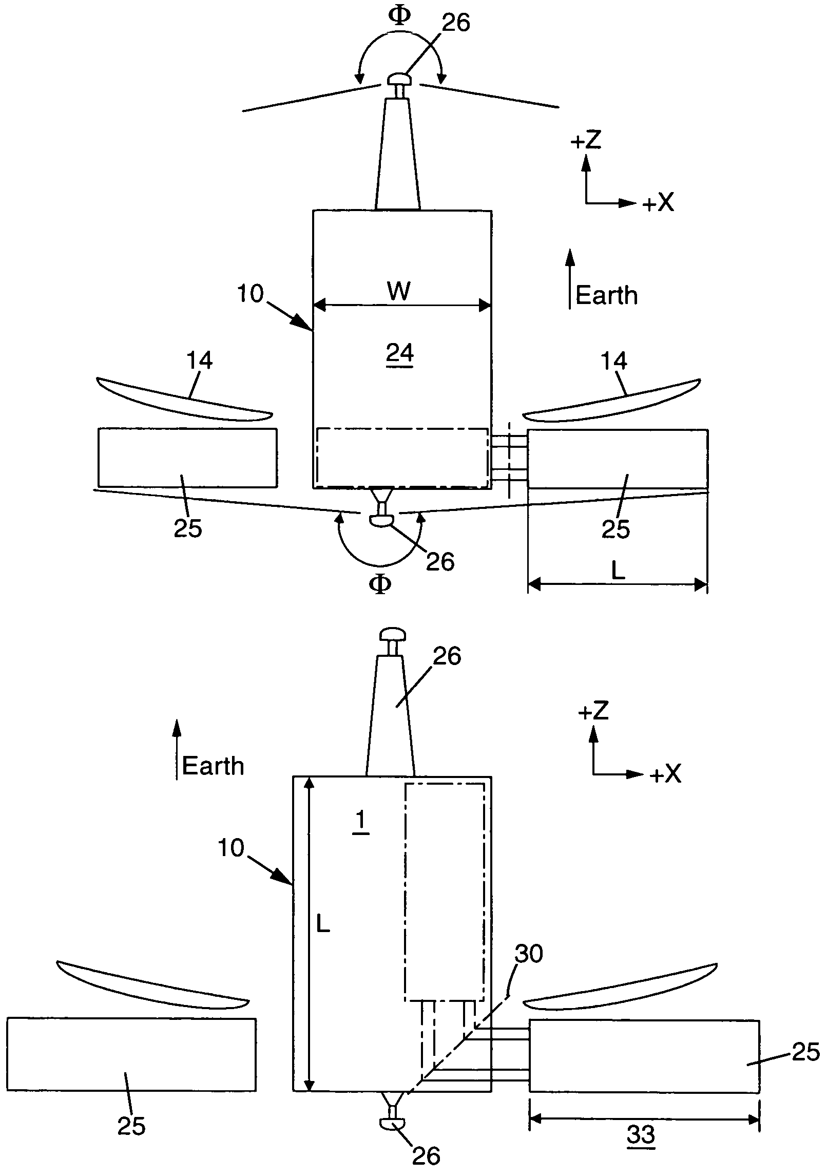
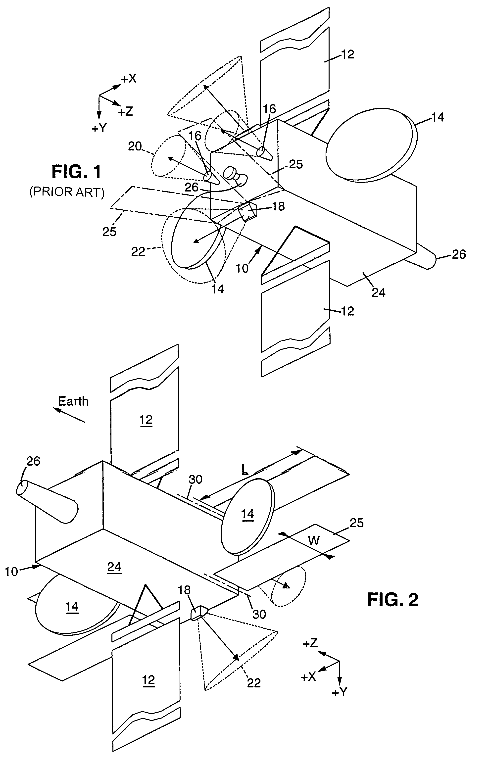
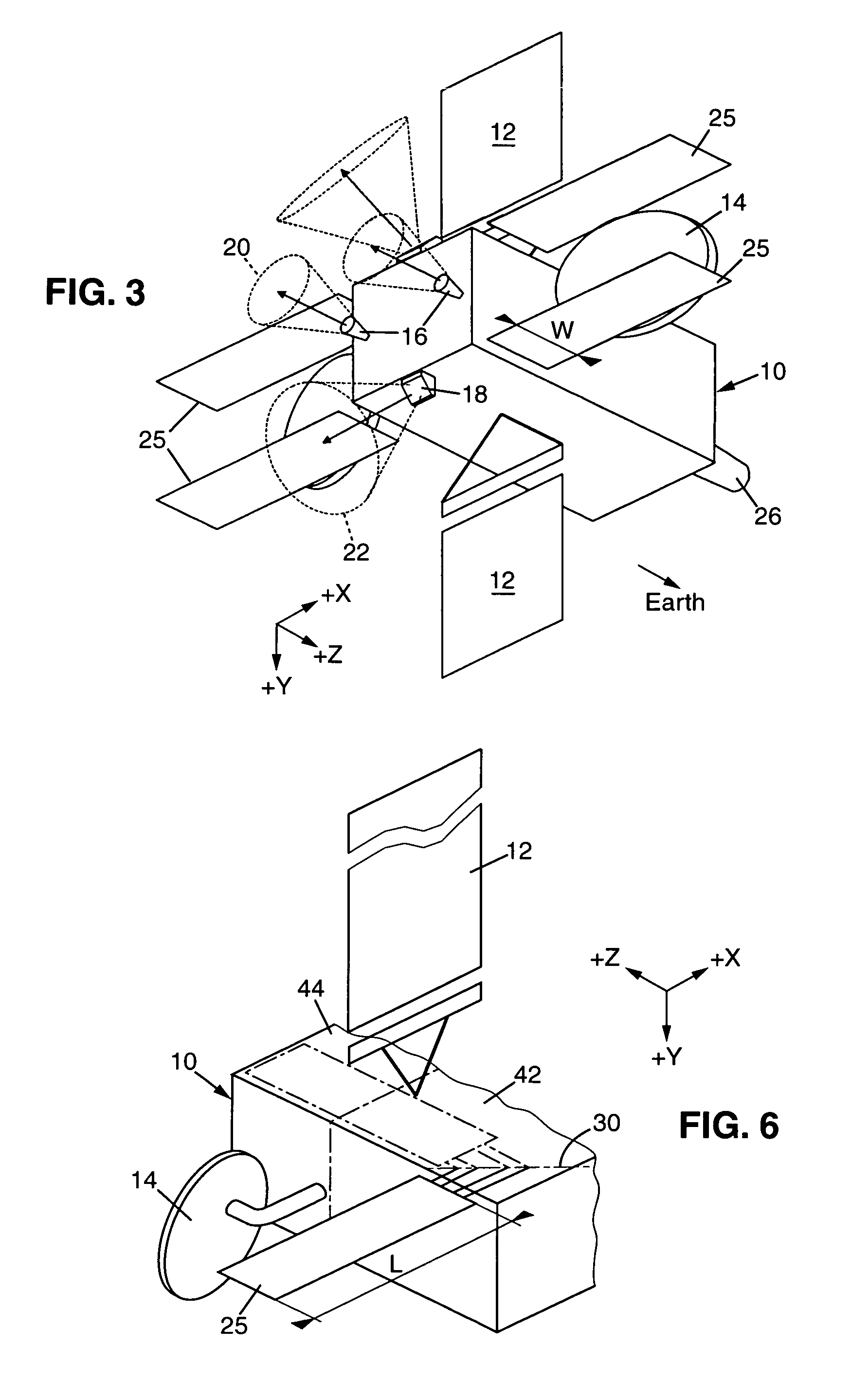
[0018]The object of the present invention is notably to provide a spacecraft with a configuration of deployable radiators which simultaneously avoids masking the field of view of the main telecommunications antenna or antennas, interfering with the plume of the propulsion generator nozzles or obstructing the field of view of an omnidirectional antenna mounted on the rear face of the spacecraft.

Problems solved by technology

The impact of these jets on surfaces causes undesirable forces, reduces the efficiency of the nozzles or ion generator and could cause damage to the surfaces.
The increase in thermal power generated on the more recent high-power satellites makes the thermal dissipation surface area of the fixed radiating surfaces inadequate.
This disposition presents a serious limitation because it does not take other issues into consideration.
For recovering the control of a satellite that has lost its nominal orientation, for example owing to a navigation error or a fault, it is not possible to use communications via the main telecommunications antennas 14, since they have a very narrow lobe.
However, in order to achieve this result, the field of view of the omnidirectional antennas must not be obscured, otherwise there may be blind regions in the coverage of the antenna which could result in loss of contact with the satellite.

Method used


Image

  • Spacecraft with extensible radiators
  • Spacecraft with extensible radiators
  • Spacecraft with extensible radiators

Examples


Embodiment Construction

[0031]The satellite whose functional architecture is shown in FIG. 2, where the elements corresponding to those in FIG. 1 carry the same reference number, has four radiators 25, in addition to the fixed radiating surfaces 24 of conventional design. Two of these four radiators are designed to tilt symmetrically about a Z-direction axis 30, from a storage position where they are flat against the north face to a deployed position where they are virtually within the extension of this north face, behind the main antenna reflectors 14 so as not to interfere with the lobe of these antennas. The width W of these radiators is thus limited to that of the free space behind the antenna reflectors 14. Their length L is limited to the width of the body in the X direction. The deployment mechanism can be of conventional design and, for example, may consist of one or more springs that, when a retaining catch is released, for example, by pyrotechnic means in response to a command from the ground, br...


PUM


Abstract

The invention concerns a space craft, such as a telecommunication geostationary satellite, comprising a body, at least one main telecommunication antenna having a specific orientation relative to the body, at least a omnidirectional antenna having a field of view opposite to that of the main antennae and at least a radiator extensible by tilting about an axis linked to the craft body between a stowing position wherein it is pressed against the body and an extended position. The axis is positioned substantially in the plane of one surface of the body parallel to the orientation of the omnidirectional antenna and to the surfaces or the surface bearing the main antenna. The radiator tilts at an angle close to 180° from a position wherein it is pressed against one surface bearing a solar panel to a position wherein it extends substantially in the plane of the surface which bears it when it is stowed.

Description

CROSS REFERENCE TO RELATED APPLICATIONS[0001]This application is a continuation of PCT / FR02 / 04428 filed Dec. 18, 2002, claiming priority of French Application No. 0200006 filed Jan. 2, 2002, which is included in its entirety by reference made hereto.BACKGROUND OF THE INVENTION[0002]1. Field of the Invention[0003]The invention relates to spacecraft fitted with heat radiators designed to dissipate the thermal energy generated on board the craft into space.[0004]It relates more especially to spacecraft designed as satellites placed into a geosynchronous orbit, and notably into a geostationary orbit, stabilized so that a given axis of the satellite stays directed toward the Earth.[0005]This latter case is that of telecommunications satellites which have main antennas designed to stay precisely oriented toward a region of the Earth when the satellite is in position.[0006]The electrical power required for the payload of spacecraft, and of geostationary satellites in particular, is supplie...

Claims


Application Information

Patent Timeline
IPC IPC(8): B64G1/58B64G1/22B64G1/44B64G1/50B64G1/66
CPCB64G1/222B64G1/503B64G1/66B64G1/2222
Inventor WALKER, ANDREW NICHOLASGUERIN, JEAN-PIERRE
Owner EADS ASTRIUM SAS
Learn More