Electro-optical apparatus, display apparatus
a technology of optical apparatus and display device, applied in the field of optical apparatus, can solve the problems of unsatisfactory transparent state, inability to obtain transparent state, etc., and achieve the effect of limiting the field of view and superior image visibility
- Summary
- Abstract
- Description
- Claims
- Application Information
AI Technical Summary
Benefits of technology
Problems solved by technology
Method used
Image
Examples
first embodiment
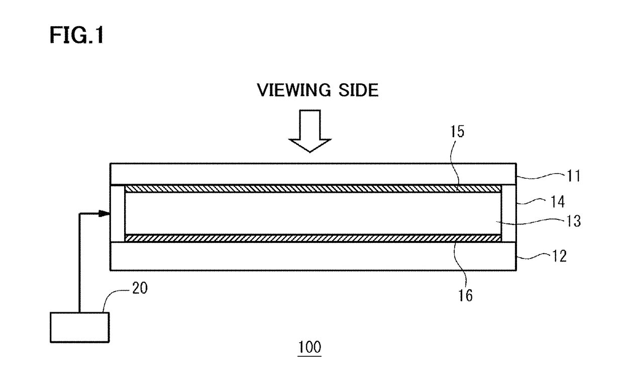
[0021]FIG. 1 is a schematic cross-sectional view showing the configuration of the electro-optical apparatus according to the first embodiment. The electro-optical apparatus 100 shown in FIG. 1 is used as a display apparatus, for example, and comprises a first substrate 11, a second substrate 12, an electrolyte layer 13, a seal member 14, and a driving device 20.
[0022]The first substrate 11 is, for example, a rigid substrate (for example, a glass substrate) having transparency. On one surface side of the first substrate 11, a first electrode 15 having fine irregularities (concave-convex configuration) is provided substantially over the entire surface thereof. Similarly, the second substrate 12 is, for example, a rigid substrate (for example, a glass substrate) having transparency. On one surface side of the second substrate 12, a second electrode 16 having fine irregularities is provided substantially over the entire surface thereof.
[0023]The first substrate 11 and the second substra...
second embodiment
[0057]FIG. 10 is a schematic cross-sectional view showing the configuration of the electro-optical apparatus according to the second embodiment. The electro-optical apparatus 100a shown in FIG. 10 is different from the apparatus 100 of the first embodiment such that it includes an insulating film 43 provided on the upper surface side of the first electrode 15, a third electrode 45 provided on the upper surface side of the first electrode 15 with the insulating film 43 interposed therebetween, the insulating film 44 provided on the upper surface side of the second electrode 16, and the fourth electrode 46 provided on the upper surface side of the second electrode 16 with the insulating film 44 interposed therebetween. Other than the above, the apparatus 100a has the same configuration as the apparatus 100. Note that the same reference numerals are given to components common to the first embodiment and the second embodiment and a detailed description thereof will be omitted.
[0058]The ...
third embodiment
[0069]FIG. 12 is a schematic cross-sectional view showing a configuration example of the electro-optical apparatus according to the third embodiment. The electro-optical apparatus 100b in FIG. 12 shows a configuration example in the case where the shape of each electrode in the above-described electro-optical apparatus 100a is changed to enable a plurality of segment display sections. Note that the same reference numerals are given to components common to the second embodiment and the third embodiment, and a detailed description thereof will be omitted.
[0070]The first electrode 15 in the third embodiment has seven segment electrodes separated from each other corresponding to each display portion of seven-segment display (refer to FIGS. 13A and 13B to be described later). The configuration of each segment electrode is the same as that of the first electrode 15 of the first and second embodiments. Lead wires (not shown in the figure) are connected to the segment electrodes respectivel...
PUM
| Property | Measurement | Unit |
|---|---|---|
| roughness | aaaaa | aaaaa |
| surface roughness | aaaaa | aaaaa |
| roughness Ra | aaaaa | aaaaa |
Abstract
Description
Claims
Application Information
 - R&D
- Intellectual Property
- Life Sciences
- Materials
- Tech Scout
- Unparalleled Data Quality
- Higher Quality Content
- 60% Fewer Hallucinations
Browse by: Latest US Patents, China's latest patents, Technical Efficacy Thesaurus, Application Domain, Technology Topic, Popular Technical Reports.
© 2025 PatSnap. All rights reserved.Legal|Privacy policy|Modern Slavery Act Transparency Statement|Sitemap|About US| Contact US: help@patsnap.com


