Eureka AIR delivers breakthrough ideas for toughest innovation challenges, trusted by R&D personnel around the world.

Curved glass plate

a glass plate and curved technology, applied in glass tempering apparatus, manufacturing tools, transportation and packaging, etc., can solve the problems of causing the glass plate to be curved, the driver or the passenger can be exposed to a significant danger, and the glass plate can be easily weakened, so as to avoid damage due to a stone or the like

Inactive Publication Date: 2005-12-01
NIPPON SHEET GLASS CO LTD
View PDF2 Cites 27 Cited by
  • Summary
  • Abstract
  • Description
  • Claims
  • Application Information

AI Technical Summary

Benefits of technology

[0025] Further, the residual plane tensile stress zone on the inner side of the residual plane compressive stress zone has a tensile stress value below 8 MPa and the entire central zone located on the inner side of the residual plane tensile stress zone comprises a residual spice compressive stress zone having a residual surface compressive stress value ranging from 10 MPa to 30 MPa. With these, even if the residual plane tensile stress zone is damaged by a cast stone or the like, there is no risk of spontaneous development of crack due to such damage. Moreover, even with sufficient strength assured, even if e.g. the driver head hits the glass plate in the event of a collision accident, the risk of his / her head being damaged is small, so that safety can be maintained. In addition, even when a crack is developed in the glass plate, this crack will hardly be formed into too small fissures in the plate which will suddenly hinder the driver's view. Therefore, it has become possible to provide a curved glass plate particularly suitable for use as an outdoor side glass plate of a laminated glass employed in an automobile.
[0027] With the second characterizing feature of the present invention, since the curved glass plate has a thickness of 1.5 to 2.5 mm which thickness is optimum for use in a curved laminated glass for an automobile. Also, the residual plane tensile stress zone provided on an outer side of the curved surface of the curved glass plate is covered with a compressive stress layer with a thickness of 0.15 mm or more in cross section thereof. As a result, when this curved glass plate is employed as an outer glass plate of a laminated glass, even when the outer surface is damaged by a stone or the like, the above features effectively restrict such damage from reaching the tensile stress layer located on the thickness-wise inner side of the residual plane tensile stress zone. Consequently, the damage due to a stone or the like can be avoided more reliably.
[0029] With the third characterizing feature of the invention, the residual surface compressive stress value of the residual plane compressive stress zone is set to range 10 MPa to 70 MPa Since the residual surface compressive stress value of the residual plane compressive stress zone is greater than 10 MPa, it is possible to assure sufficient for the curved glass plate. Further, since the residual surface compressive stress value of the residual plane compressive stress zone is less than 70 MPa, it is possible to prevent the tensile stress value of the residual plane compressive stress zone located on the inner side of the residual plane compressive stress zone from becoming too large. As a result, the damage due to a stone or the like can be avoided even more reliably.

Problems solved by technology

Hence, with lapse of time, spontaneous development of a crack will occur, thus eventually inviting break of the curved glass plate.
Also, if the residual surface compressive stress value C of the entire central zone is too small, this will result in danger of weakness of the glass plate against application of an external force thereto.
However, in the event of a collision accident, the driver or the passenger can be exposed to a significant danger if his / her head hits the front windshield.
Moreover, once a crack has been formed in the curved glass plate, this crack will likely be developed into too small fissures of the plate, which will suddenly hinder the drivers view, hence again presenting danger.
None of the above-cited Patent Documents 1-8 have successfully coped with these problems.

Method used

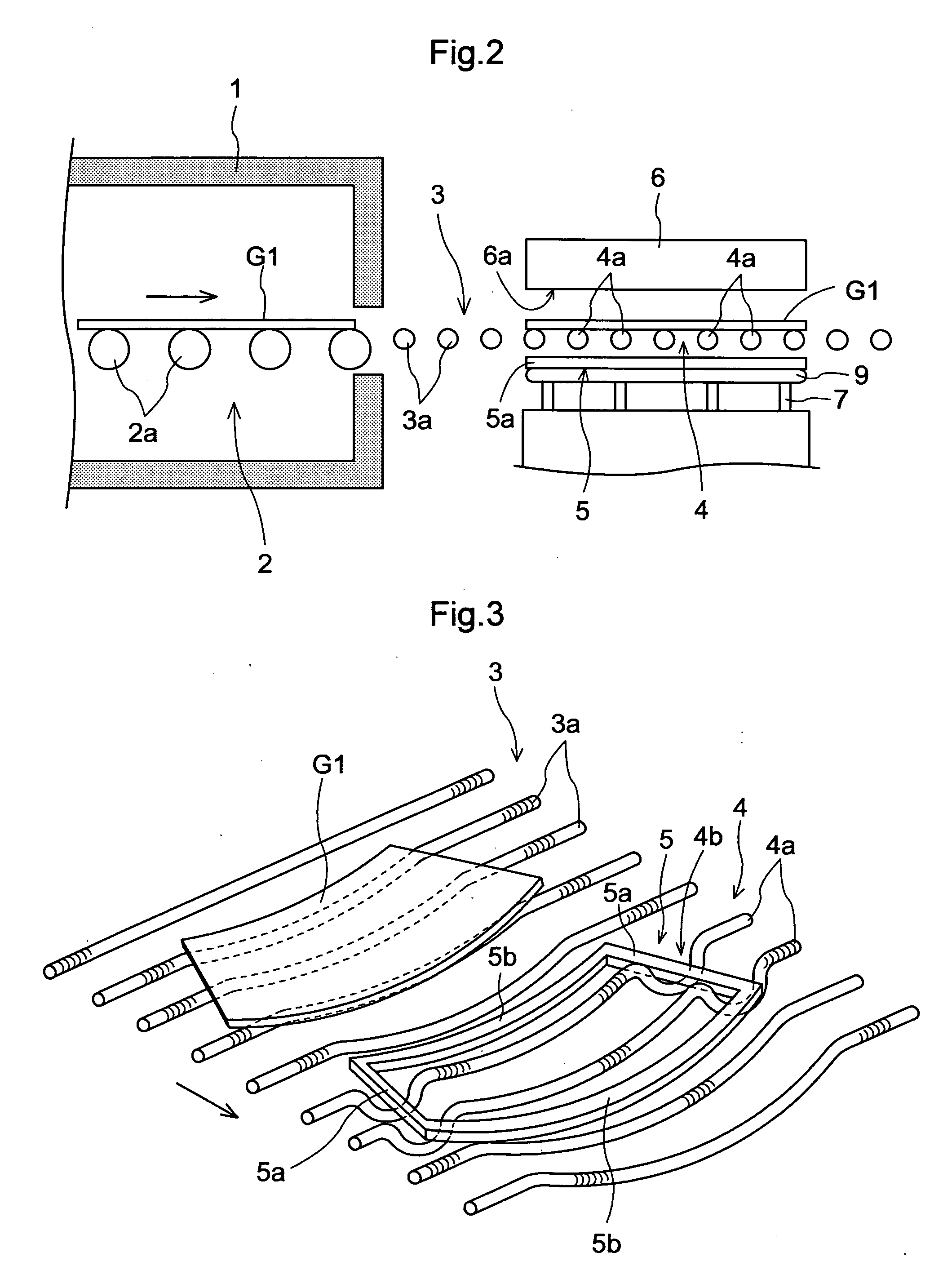

Image

  • Curved glass plate
  • Curved glass plate
  • Curved glass plate

Examples


Embodiment Construction

[0037] A preferred embodiment of a cared glass plate relating to the present invention will be now described in details with reference to the accompanying drawings.

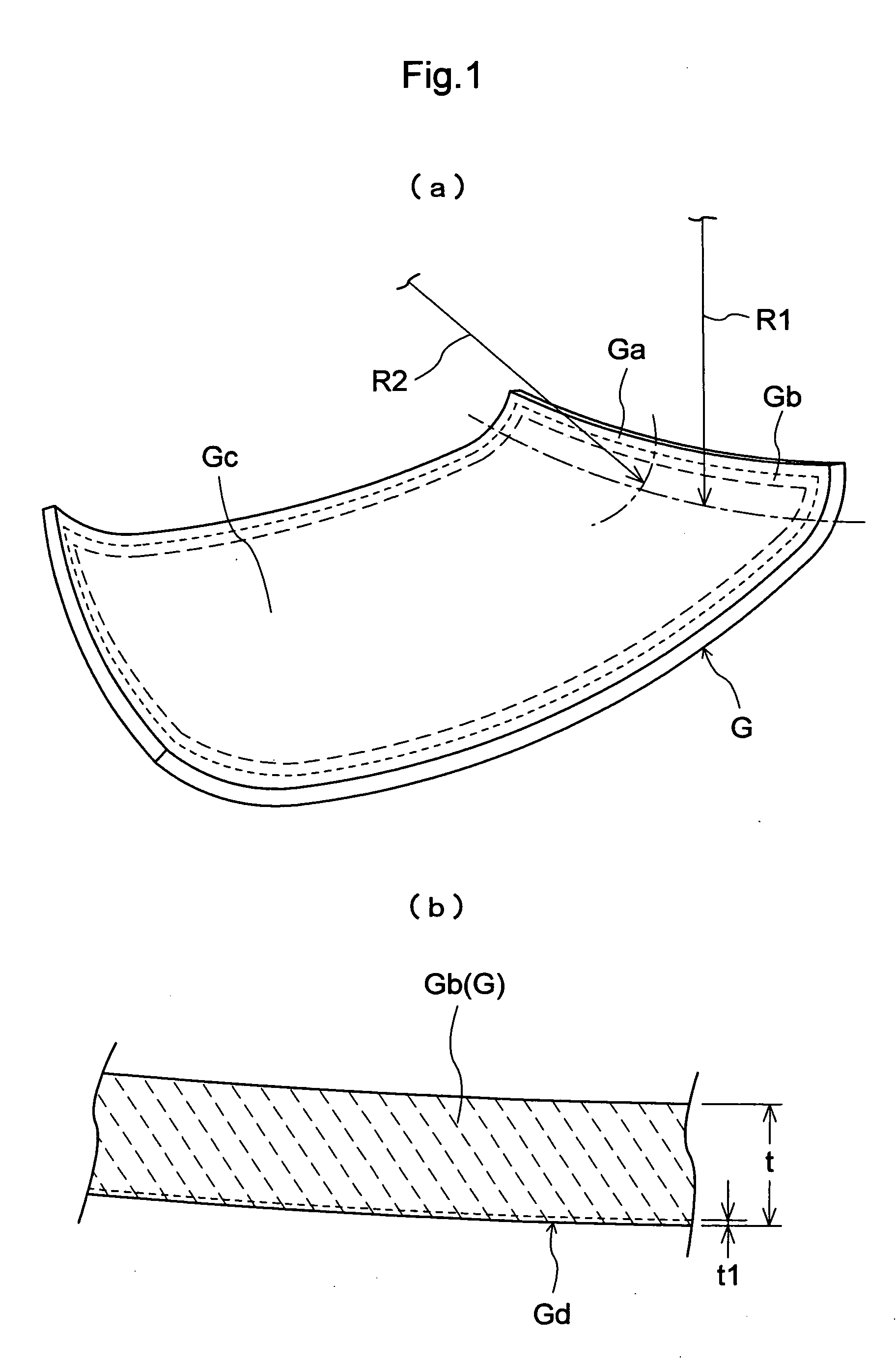
[0038] The curved glass plate relating to the present invention is particularly suitable for use as an outdoor side glass plate of a laminated glass employed in an automobile. As shown in FIG. 1, this cured glass plate G has a thickness (t) ranging from 1.5 to 2.5 mm and includes a curved peripheral surface portion where R1×R2 is 1,500,000 mm2 or less, R1 being a radius of curvature determined in a direction parallel to an edge of the glass plate, R2 being a radius of curvature determined in a direction normal to said direction.

[0039] Further, this curved glass plate shown in FIG. 1 is for use in particular as an outer side glass plate of a laminated glass employed in a front windshield of an automobile. Here, the above R2 is represented by a radius of curvature of the curved portion extending by 50 mm from the right or...


PUM

PropertyMeasurementUnit
Thicknessaaaaaaaaaa
Thicknessaaaaaaaaaa
Pressureaaaaaaaaaa

Abstract

A carved glass plate ha a curved peripheral spice portion where R1×R2 is 1,500,000 m2 or less, R1 being a radius of curvature determined in a direction parallel to an edge of the glass plate, R2 being a radius of curvature determined in a direction normal to the direction. The curved peripheral surface portion includes a residual plane compressive stress zone and a residual plane tensile stress zone on the inner side of the residual plane compressive stress zone, the residual plane tensile stress zone having a tensile stress value below 8 MPa The glass plate has also a central portion located on the inner side of the residual plane tensile stress zone. This entire central zone is a residual surface compressive stress zone having a residual surface compressive stress value ranging from 10 MPa to 30 MPa.

Description

BACKGROUND OF THE INVENTION [0001] 1. Field of the Invention [0002] The present invention relates to a curved glass plate including a curved peripheral surface portion where R1×R2 is 1,500,000 mm2 or less, R1 being a radius of curvature determined in a direction parallel to an edge of the glass plate, R2 being a radius, of curvature determined in a direction normal to said direction. [0003] 2. Background Art [0004] Such curved glass plate is for use as e.g. an outer glass plate of a laminated glass employed in a front or rear windshield or a side window of an automobile. In particular, such curved glass plate has a significantly or conspicuously bulging portion with a large curvature. In recent years, such glass plate having a large curvature has often been employed in e.g. front windshield of the automobile. [0005] Such curved glass plate as described above is known from e.g. Japanese Patent Application National Publication No. 8-501272 and Japanese Patent Application “Kokai” No. 5...

Claims


Application Information

Patent Timeline
IPC IPC(8): C03B23/03B32B17/00B32B17/10C03B23/025C03B27/04C03B27/044
CPCB32B17/10036B32B17/10091C03B23/0256C03B23/0258C03B27/0404C03B27/0413C03B27/0442Y10T428/315
Inventor YOSHIZAWA, HIDEO
Owner NIPPON SHEET GLASS CO LTD
Why Eureka
Eureka Blog
Learn More